
System and method of solar flux concentration for orbital debris remediation

a solar flux and orbital debris technology, applied in the field of solar concentrators, can solve the problems of space debris a hazard to future space vehicles, excessive power requirements for ground lasers, and large propagation losses of earth-based lasers, and achieves compact volume, large surface area, and effective system implementation.

Active Publication Date: 2014-10-28
THE JOHN HOPKINS UNIV SCHOOL OF MEDICINE
View PDF11 Cites 6 Cited by
  • Summary
  • Abstract
  • Description
  • Claims
  • Application Information

AI Technical Summary

Benefits of technology

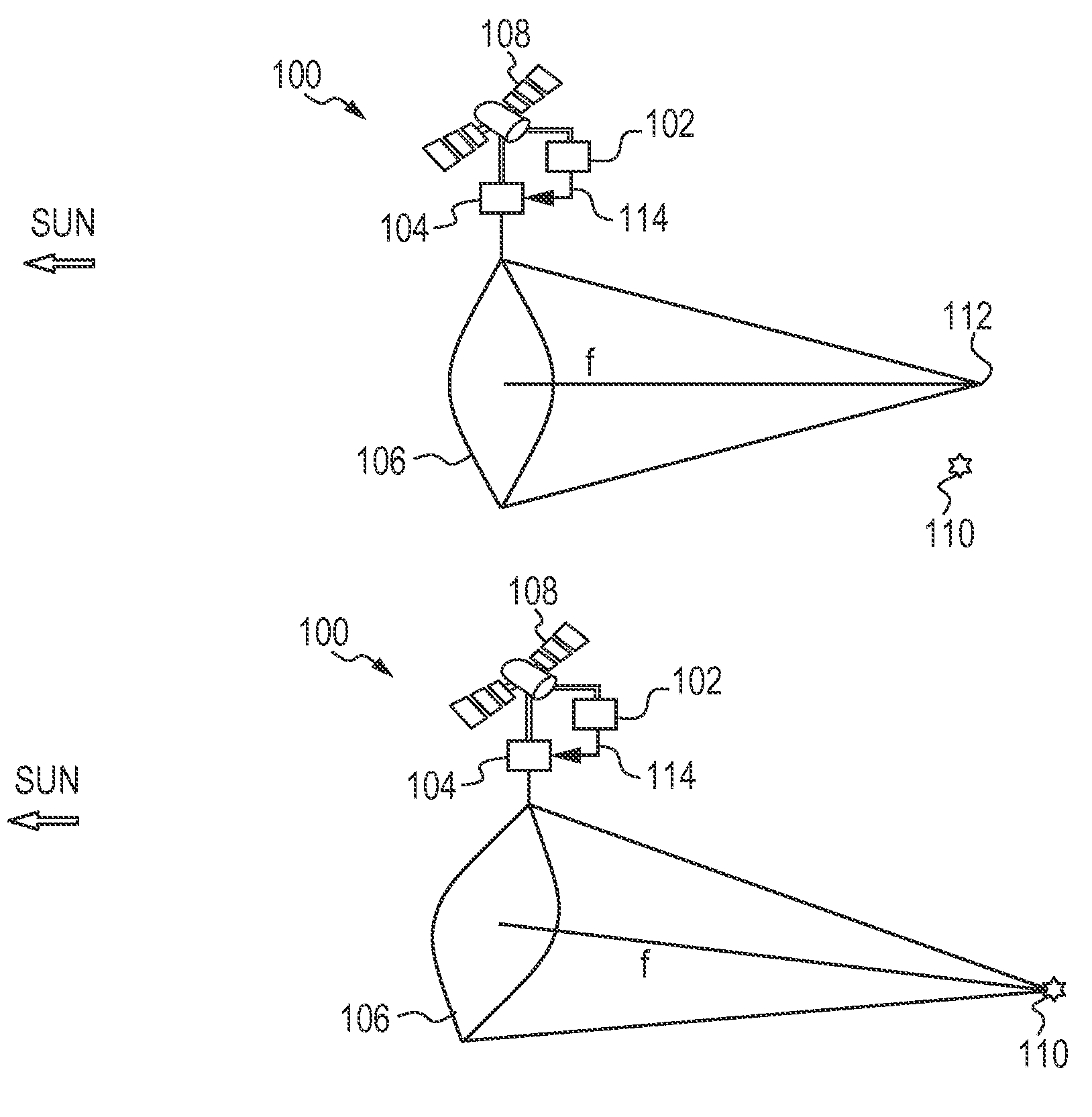
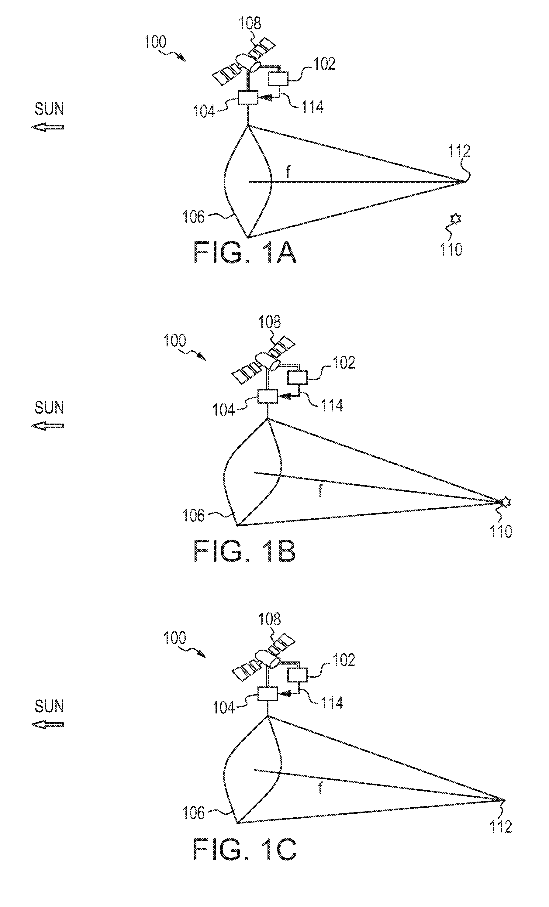
The present invention provides a compact system that can be easily transported to space, but provides a large surface area after deployment. It also requires a less demanding pointing and control system than its ground-based equivalent. The system has a unique focusing arrangement that allows for precise tracking of objects over a large range of distances. The use of smaller apertures and a rotational focus control method enable greater solar flux concentration. The overall effect of the invention is a highly efficient and effective space-based system.

Problems solved by technology

Space debris is a hazard to future space vehicles because of the risk of collision.
Earth-based lasers suffer huge propagation losses from atmospheric attenuation and turbulence, cloud obscuration, and pointing errors over the longer distances required to intercept debris.
To compensate for the huge propagation losses, prohibitively high transmitter flux is required, making power requirements for ground lasers excessive and costly.
The relatively low wall-plug efficiency of current laser technology makes space deployment very costly and virtually impractical relative to the launch costs, which place a severe limit on the size, weight and power (SWaP) of effective laser platforms.
Ordinarily, a typical focusing system has a lot of large and heavy optical components needed to enable high quality imaging, but solar flux concentration has less demanding requirements on surface curvature, especially using different technology (such as diffractive membrane optics), and the mass and bulk of conventional optical components make it impractical for spacecraft deployment of such large apertures.

Method used


Image

  • System and method of solar flux concentration for orbital debris remediation
  • System and method of solar flux concentration for orbital debris remediation
  • System and method of solar flux concentration for orbital debris remediation

Examples


Embodiment Construction

[0002]This invention was made with government support under contract number HR0011-06-D-0003 awarded by the Defense Advanced Research Projects Agency (DARPA). The government has certain rights in the invention.

BACKGROUND OF THE INVENTION

[0003]1. Field of the Invention

[0004]The present invention relates to solar technologies, and more particularly to solar concentrators.

[0005]2. Description of the Related Art

[0006]Space debris includes man-made non-functional objects that are either in Earth orbit or re-entering the atmosphere. Some examples of space debris include non-functional satellites and fragments from space vehicle explosions or collisions. Space debris is a hazard to future space vehicles because of the risk of collision.

[0007]Space debris can be separated into three categories by size: Category 1 (10 cm). In particular, there are about 100,000 to 10,000,000 pieces of Category 2 space debris within 1600 km of the Earth's surface. Thus, it is important to remediate the large ...


PUM


Abstract

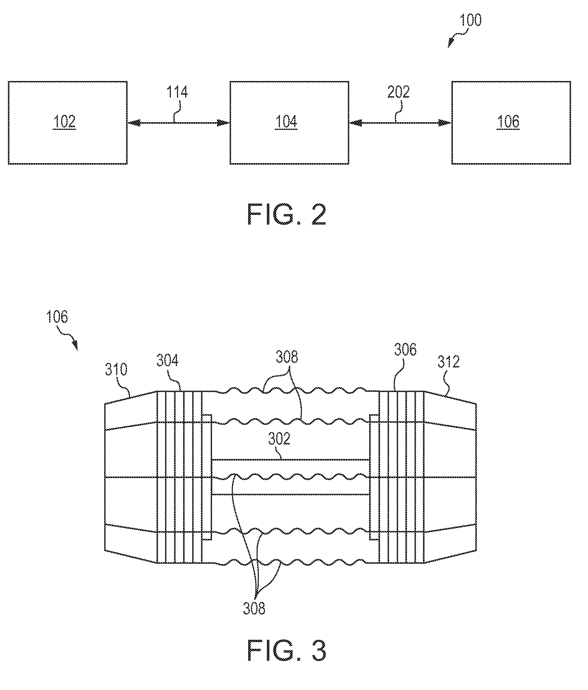
A system for concentrating solar radiation onto a space debris object to vaporize includes a focusing system, an object tracking system and a positioning system. The focusing system has a total focal length fT, and includes a first focusing device and a second focusing device. The first focusing devices change from a compact state to a deployed state, and the compact surface area is less than the deployed surface area. The object tracking system determines the location of the object. The positioning system orients the focusing system such that solar radiation focuses on the space debris object.

Description

CROSS-REFERENCE TO RELATED APPLICATION[0001]This application claims priority to and the benefit of prior-filed co-pending U.S. Provisional Application No. 61 / 424,204, filed Dec. 17, 2010, the content of which is herein incorporated by reference in its entirety.STATEMENT OF GOVERNMENTAL INTEREST[0002]This invention was made with government support under contract number HR0011-06-D-0003 awarded by the Defense Advanced Research Projects Agency (DARPA). The government has certain rights in the invention.BACKGROUND OF THE INVENTION[0003]1. Field of the Invention[0004]The present invention relates to solar technologies, and more particularly to solar concentrators.[0005]2. Description of the Related Art[0006]Space debris includes man-made non-functional objects that are either in Earth orbit or re-entering the atmosphere. Some examples of space debris include non-functional satellites and fragments from space vehicle explosions or collisions. Space debris is a hazard to future space vehic...

Claims


Application Information

Patent Timeline
Patent Type & Authority Patents(United States)
IPC IPC(8): G02B3/08F24J2/08B64G1/22B64G1/52B64G1/44F24S23/30
CPCB64G1/222F24J2/085G02B3/08B64G1/44B64G1/52B64G1/66B64G1/24B64G1/32B64G1/285B64G1/361B64G1/363B64G1/26F24S23/31B64G1/244Y02E10/40B64G1/2226
Inventor BOONE, BRADLEY, G.
Owner THE JOHN HOPKINS UNIV SCHOOL OF MEDICINE
Learn More