

Connecting device for kill/choke lines between a riser and a floating drilling vessel
a technology of connecting device and riser, which is applied in the direction of drilling machines and methods, bulkheads/piles, and fluid removal. it can solve the problems of insufficient compensation of vertical relative movements, and achieve the effect of improving the stability of the bore hole wall and improving the hole to manage the pressur
- Summary
- Abstract
- Description
- Claims
- Application Information
AI Technical Summary
Benefits of technology
Problems solved by technology
Method used
Image

Examples
Embodiment Construction
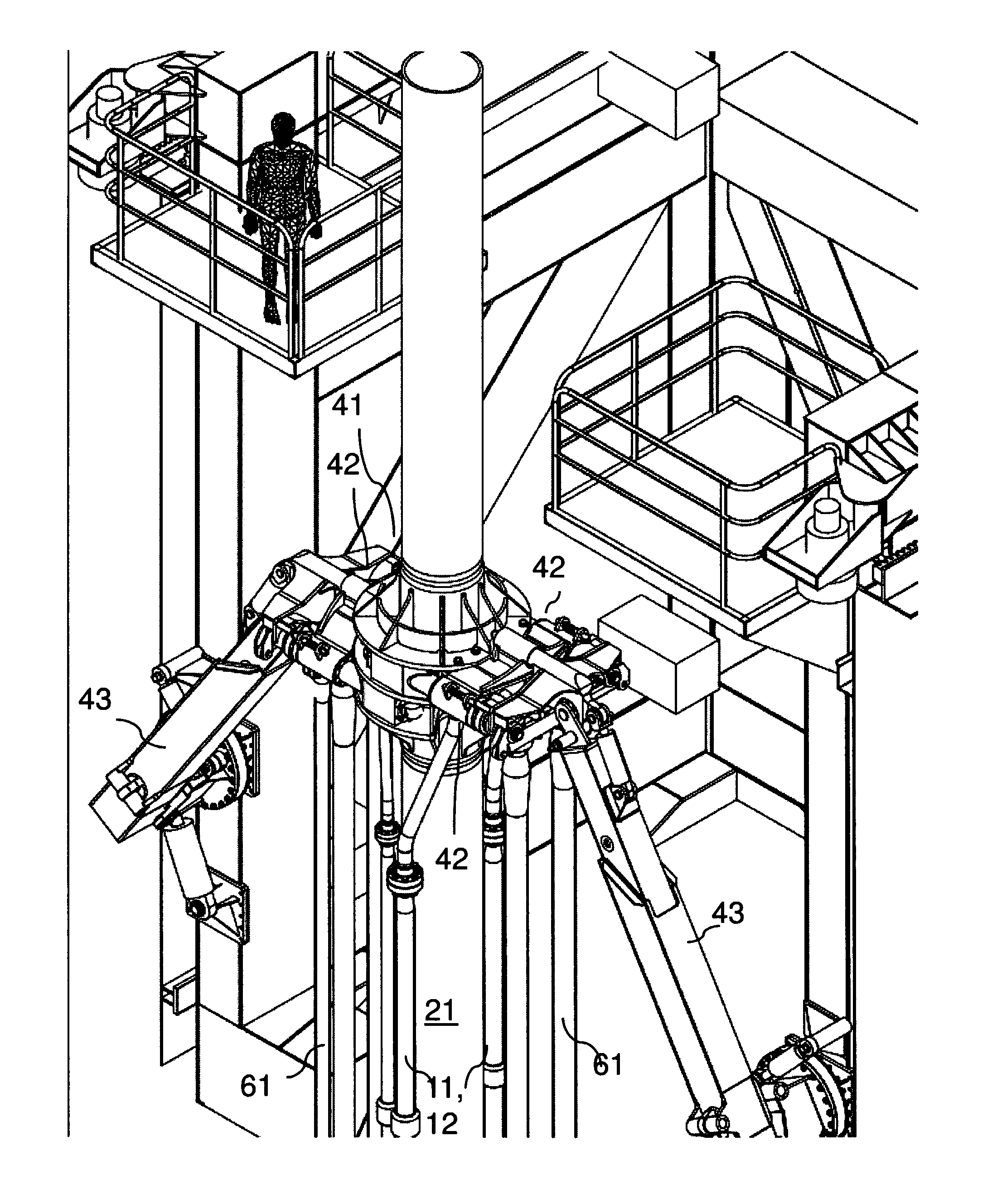
[0060]FIG. 9 illustrates an embodiment of the invention. The drawing is a cross-section through a drilling platform through a central portion of the drilling deck and auxiliary platforms below the drilling deck, and through the cellar deck. The drawing is also a cross-section through a moonpool which extends athwart of the vessel and wherein is arranged a skid for a BOP which may be run in from the side and in under the opening in the drilling deck. The riser here hangs from the top drive (not shown) and down through the opening in the drilling deck and the diverter housing and extends further down to the BOP which hangs in a desired elevation above the wellhead. According to this embodiment of the invention, horizontally directed kill- and choke connector manifolds, with kill- and choke hoses from the platform's side, are arranged on the skid and arranged for being guided in into two corresponding and oppositely directed horizontally directed kill- and choke manifolds on the riser'...
PUM
 Abstract
Description
Claims
Application Information