Manifold insert having distribution guides and fuel cell stack comprising the same

a technology of distribution guides and manifold inserts, which is applied in the direction of battery/fuel cell control arrangement, electric devices, cell components, etc., can solve the problems of increasing output voltage deviation, deteriorating fuel efficiency, and non-uniform flow rate, so as to reduce output voltage deviation, prevent local flow instability of electrodes, and stable performance of unit cells

Active Publication Date: 2014-11-11
HYUNDAI MOTOR CO LTD +1
View PDF7 Cites 1 Cited by
  • Summary
  • Abstract
  • Description
  • Claims
  • Application Information

AI Technical Summary

Benefits of technology

[0031]The present invention provides a manifold insert having a plurality of improved flow distribution guides, and a fuel cell stack comprising the same. The present invention reduces output voltage deviation due to flow instability between unit cells and prevents local flow instability of electrodes by stably distributing the flow of fluid (such as air, hydrogen, and coolant) supplied to a fuel cell stack, thereby maintaining a stable performance of the unit cells.

Problems solved by technology

This increase causes non-uniformity of the flow rate of gas supplied to channels of the unit cells via the manifold for distributing the gas.
Therefore, if the number of unit cells exceeds a predetermined range, the flow rate range for voltage stabilization is restricted or the stoichiometric ratio should be maintained at a high level, which causes deterioration of fuel efficiency.
However, as shown in FIG. 2, during a rapid change in load according to a driver's request, such as sudden acceleration, the flow rates according to the positions of the unit cells are not uniform, thus increasing the output voltage deviation.
Therefore, an excessive amount of gas is supplied to the unit cells, but there are regions where the flow rate is insufficient due to a partial reduction in gas pressure, which results in a reduction in power generation.
As a result, this leads to a limitation in power generation and, if this non-uniformity of the flow rate of gas supplied to the unit cells is out of the control range, it may develop into a failure in start-up and a shutdown of the vehicle.
First, according to Patent Literature 1, the separation window provided for the flow stabilization should be formed in the manifold during manufacturing of the bipolar plate, and thus it is difficult to mass produce the bipolar plates used in multiple unit cells (e.g. 400 unit cells) per fuel cell stack. Moreover, a predetermined length of the separation window is formed in a straight line and the plurality of stepped portions is formed thereafter, but the flow instability is not completely solved. Therefore, the porous flow obstacle in the form of a net and the dummy cell are further provided. However, the shape of the porous flow obstacle is complex, and thus its production is difficult. Moreover, the unstable flow region is filled with the dummy cell, which causes an unnecessary increase in volume and cost.
However, the production of the fuel cell stack is thereby complicated, reducing the productivity.
Moreover, in Patent Literature 3, when the cross-sectional area of the manifold is reduced toward the center to control the amount of heat generated, the flow is unstable, thereby causing voltage instability and damage to the unit cells.
Furthermore, in Patent Literature 4, when the flow stabilization manifold is formed in the bipolar plate, the production of the bipolar plate is complicated and the production cost increases.
In addition, in Patent Literature 5, when the buffer is provided on the outside of the fuel cell stack, the unused space of the system increases, and thus it is difficult to form the fuel cell stack in a compact size.
Moreover, it is difficult to immediately satisfy the driver's request such as sudden acceleration using this system.

Method used


Image

  • Manifold insert having distribution guides and fuel cell stack comprising the same
  • Manifold insert having distribution guides and fuel cell stack comprising the same
  • Manifold insert having distribution guides and fuel cell stack comprising the same

Examples


Embodiment Construction

[0056]Hereinafter reference will now be made in detail to various embodiments of the present invention, examples of which are illustrated in the accompanying drawings and described below. While the invention will be described in conjunction with exemplary embodiments, it will be understood that present description is not intended to limit the invention to those exemplary embodiments. On the contrary, the invention is intended to cover not only the exemplary embodiments, but also various alternatives, modifications, equivalents and other embodiments, which may be included within the spirit and scope of the invention as defined by the appended claims.

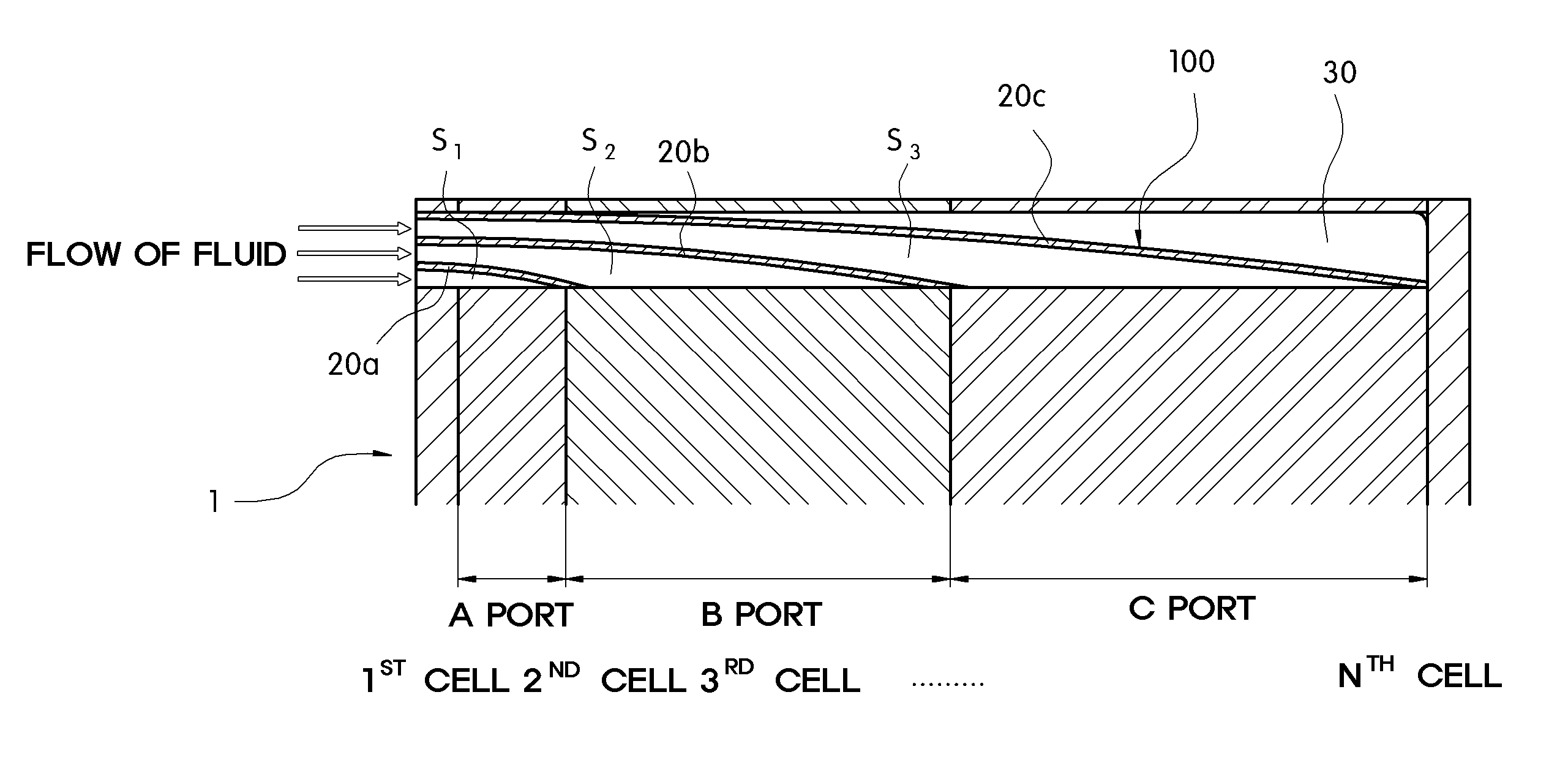
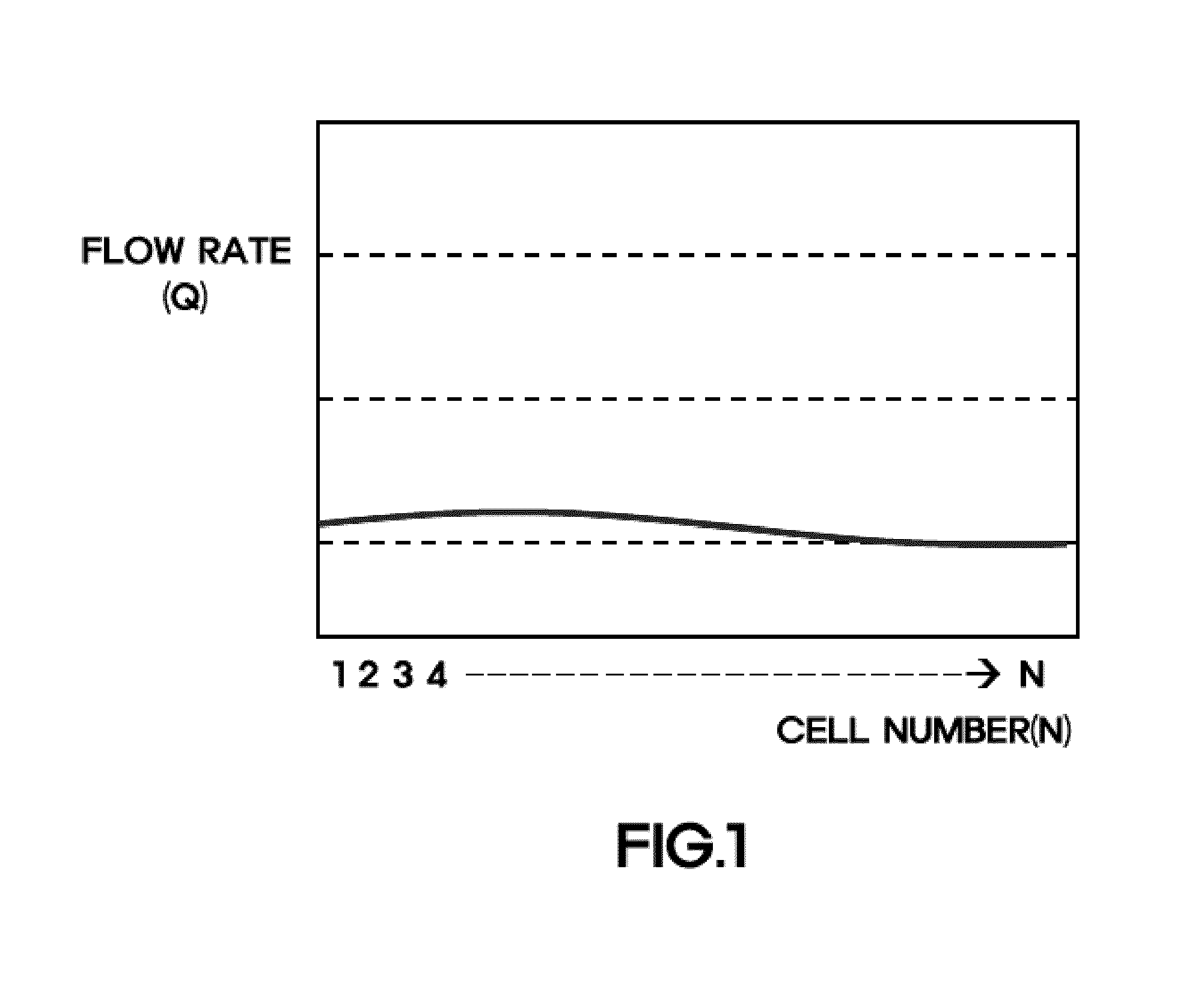
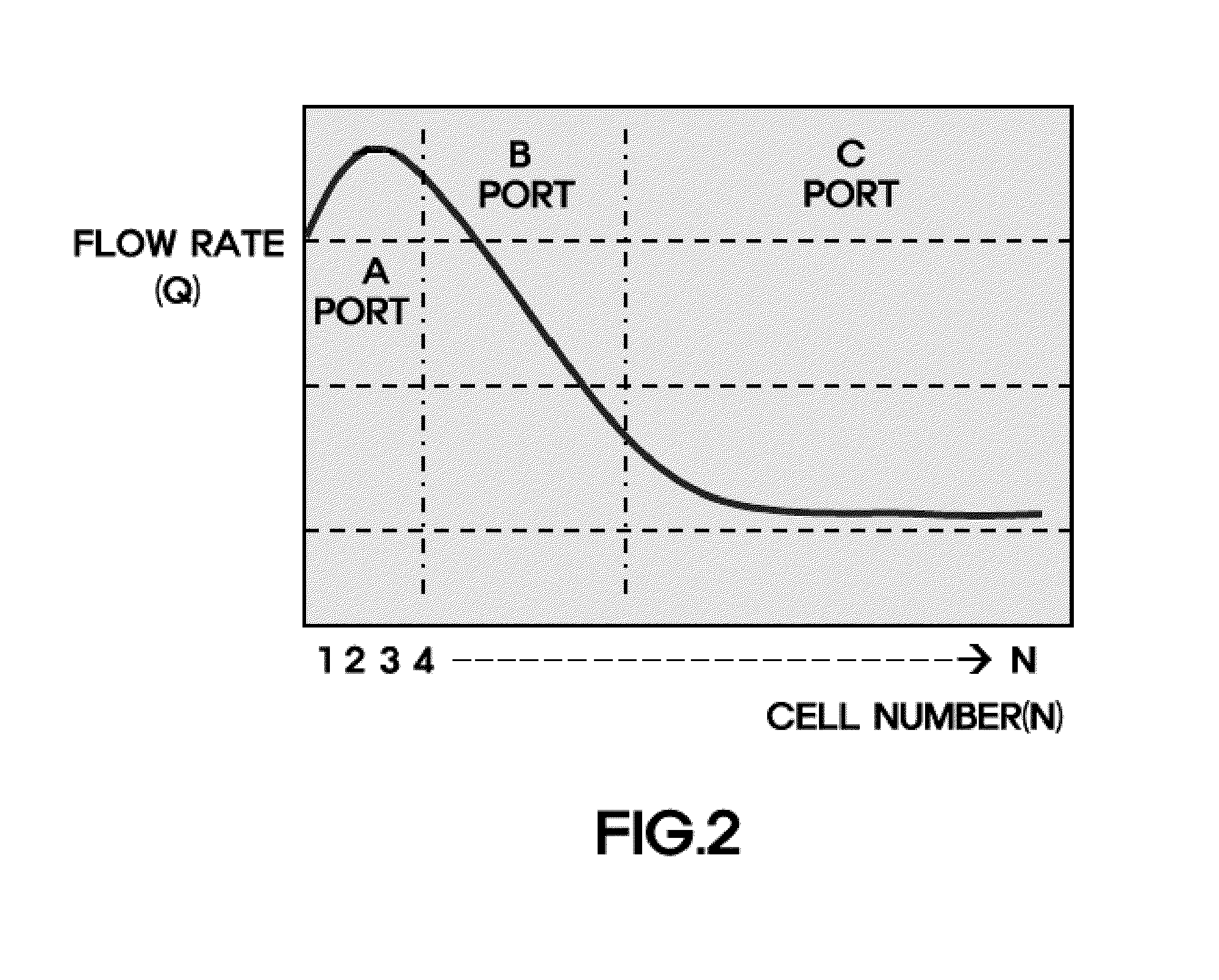
[0057]The present invention provides a manifold insert which distributes the flow of fluid supplied to a fuel cell stack, and a fuel cell stack comprising the same. The manifold insert comprises a plurality of improved flow distribution guides, including guide flow fields whose cross-sectional areas are changed to overcome flow instabilit...


PUM

PropertyMeasurementUnit
currentaaaaaaaaaa
distanceaaaaaaaaaa
flow ratesaaaaaaaaaa

Abstract

A manifold insert installed in a fuel cell having distribution guides is provided. The manifold insert is configured to form a flow field from an inlet port of fluid to an outlet port connected to a fuel cell stack. This manifold insert includes a plurality of distribution guides that divide the flow field from the inlet port to the outlet port such that the fuel cell stack is divided into a plurality of regions according to the distance from the inlet port. The distribution guides have surfaces that are at least partially curved such that the flow of the fluid from the inlet port to the outlet port is changed by the curved surfaces and form a plurality of guide flow fields such that the fluid is supplied to the divided regions of the fuel cell stack along the plurality of guide flow fields at different flow rates.

Description

CROSS-REFERENCE TO RELATED APPLICATION[0001]This application claims under 35 U.S.C. §119(a) the benefit of Korean Patent Application No. 10-2010-0114456 filed Nov. 17, 2010, the entire contents of which are incorporated herein by reference.BACKGROUND[0002](a) Technical Field[0003]The present invention relates to a manifold insert having distribution guides and a fuel cell stack comprising the same. More particularly, it relates to a manifold insert having a plurality of distribution guides which can reduce output voltage deviation and prevent flow instability by stably distributing the flow of fluid supplied to a fuel cell stack, and a fuel cell stack comprising the same.[0004](b) Background Art[0005]A fuel cell is an electricity generation system that electrochemically converts chemical energy directly into electrical energy in a fuel cell stack instead of converting chemical energy of fuel into heat by combustion. The fuel cell can be applied to the electric power supply of small-...

Claims


Application Information

Patent Timeline
Patent Type & Authority Patents(United States)
IPC IPC(8): H01M8/10B60L11/18H01M8/04B60L3/00H01M8/24H01M2/38
CPCH01M2008/1095B60L11/1898H01M8/2485B60L2240/36B60L3/0053Y02T90/34H01M8/04089Y02E60/50B60L50/72B60L58/33Y02T90/40H01M8/2483
Inventor KO, HAENG JINKUM, YOUNG BUMNAM, GI YOUNGKIM, YUN SEOK
Owner HYUNDAI MOTOR CO LTD
Why Eureka
Try Eureka