
Method of position sensorless control of an electrical machine

a technology of position sensor and electrical machine, which is applied in the direction of motor/generator/converter stopper, dynamo-electric converter control, pulse technique, etc., can solve the problem that the observation based position sensorless control method of back electromotive force (bemf) for interior permanent magnet (ipm) machines may not work well at speeds close to standstill

Active Publication Date: 2014-11-11
VESTAS WIND SYST AS
View PDF62 Cites 10 Cited by
  • Summary
  • Abstract
  • Description
  • Claims
  • Application Information

AI Technical Summary

Benefits of technology

This method provides robust and accurate position estimation and control for electrical machines across a wide speed range, independent of PWM modulation schemes and stator resistance variations, making it suitable for both low and high-speed operations.

Problems solved by technology

Electrical signal wires of shaft mounted position encoder sensors reduce the robustness of the overall generator control system due to significant mechanical vibration that exists on the turbine driven train.
Conventional Back Electromotive Force (Bemf) observation based position sensorless control methods for Interior Permanent Magnet (IPM) machines may not work well at speeds close to standstill where the generator Bemf voltage level is very low.
By principle, this prior art method is sensitive to stator resistance variation and it may not be applicable for high speed operation.
These assumptions make prior art methods sensitive to stator resistance variation and they are not suitable for high speed operation.

Method used


Image

  • Method of position sensorless control of an electrical machine
  • Method of position sensorless control of an electrical machine
  • Method of position sensorless control of an electrical machine

Examples


Embodiment Construction

[0006]Embodiments of the invention generally relate to a position sensorless control methodology for electrical machines.

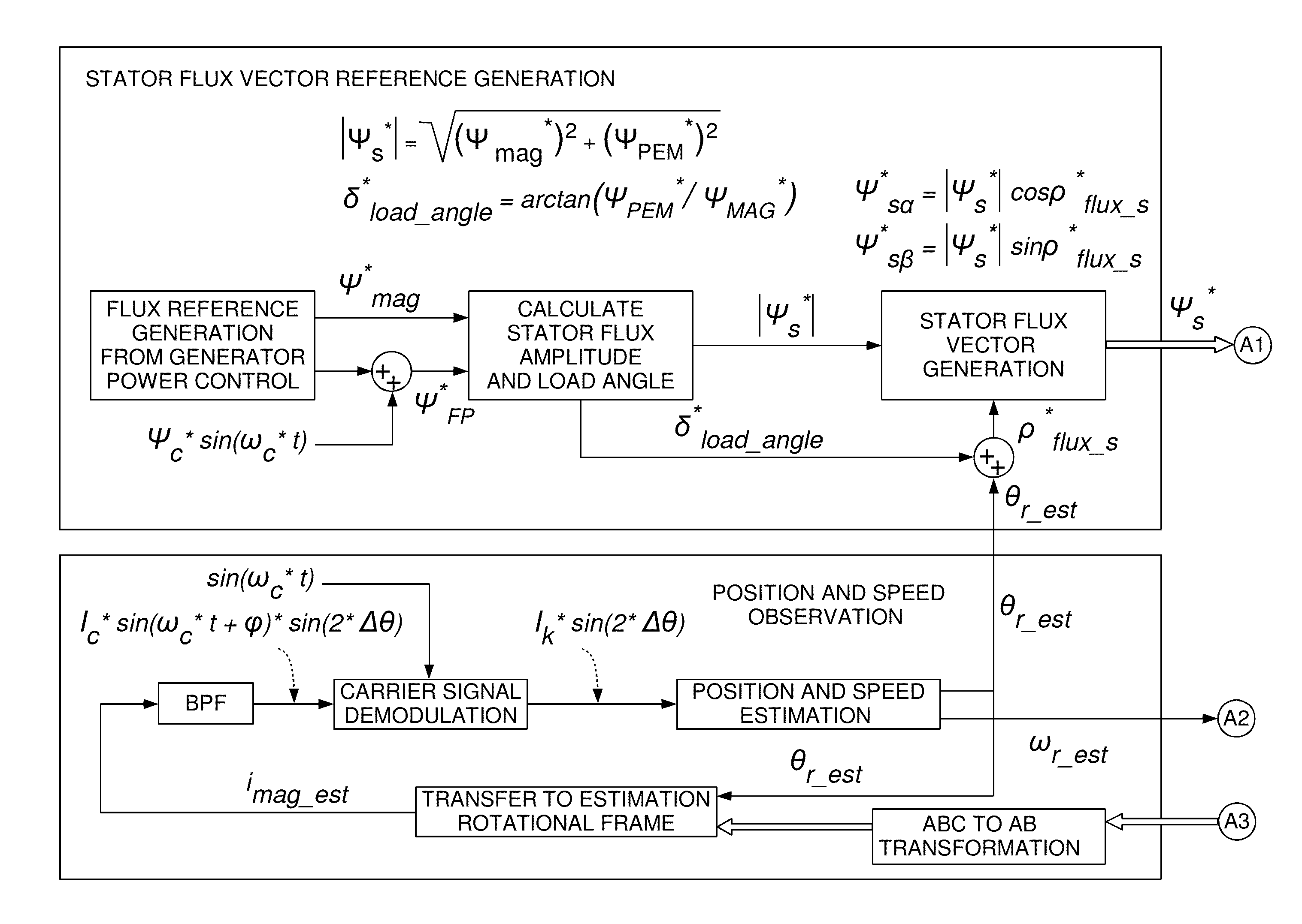
[0007]A first aspect of the invention provides a method for position sensorless control of an electrical machine, the method comprising[0008]generating a flux vector reference signal,[0009]modulating the flux vector reference signal by injecting a high frequency signal carrier,[0010]determining a position error function signal from the modulated flux vector reference signal,[0011]estimating the speed of the rotor,[0012]estimating an angular position of the rotor from the estimated speed, and[0013]applying the estimated rotor speed and the estimated angular rotor position to control the electrical machine.

[0014]In a second aspect, there is provided a wind turbine comprising an electrical machine, and an apparatus for position sensorless control of the electrical machine, the apparatus being adapted to carry out the methods of the first aspect.

[0015]In another aspec...


PUM


Abstract

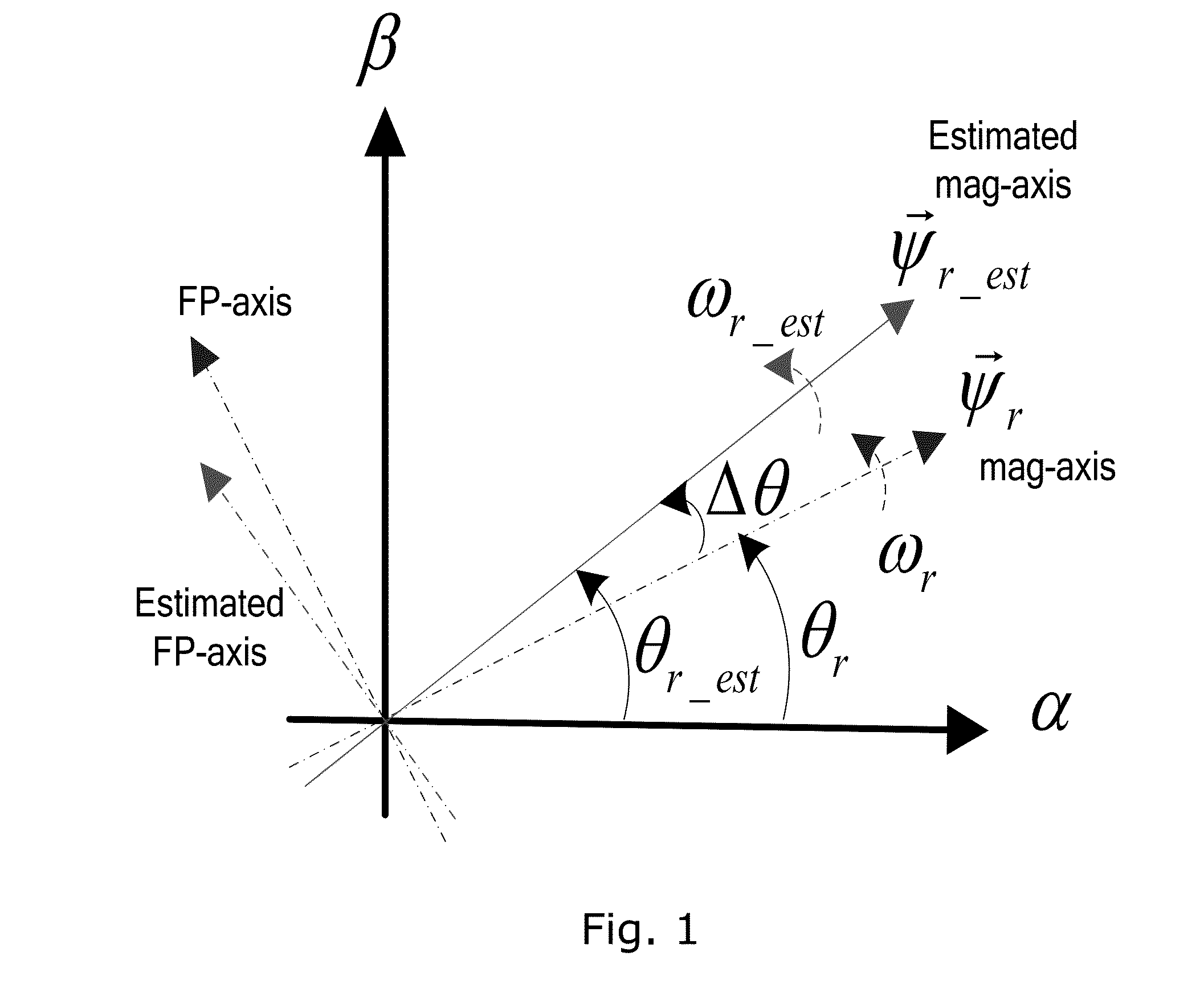
A position sensorless control methodology for electrical machines using high frequency flux vector signal injection in the estimated rotor flux rotational reference frame is provided. In one aspect, the estimated position error function is derived directly from the stator flux equation without any simplification. The method is applicable for electrical generator motoring mode operation from standstill and power generation mode operation.

Description

FIELD OF THE INVENTION[0001]Embodiments of the present invention relate to a position sensorless control methodology for electrical machines, in particular, determining a rotor position using a flux vector carrier signal injection.BACKGROUND OF THE INVENTION[0002]Electrical signal wires of shaft mounted position encoder sensors reduce the robustness of the overall generator control system due to significant mechanical vibration that exists on the turbine driven train.[0003]Conventional Back Electromotive Force (Bemf) observation based position sensorless control methods for Interior Permanent Magnet (IPM) machines may not work well at speeds close to standstill where the generator Bemf voltage level is very low.[0004]The performance of the conventional high frequency carrier signal injection methods, which utilizes the inductance saliency of IPM machine, is derived from the stator voltage equation. Simplification is made to ignore the effect of stator resistance variation and the ef...

Claims


Application Information

Patent Timeline
Patent Type & Authority Patents(United States)
IPC IPC(8): H02P6/22
CPCH02P21/00H02P6/183
Inventor CAO, SHU YULI, BINGTRIPATHI, ANSHUMANHELLE, LARS
Owner VESTAS WIND SYST AS
Learn More