Device for broadband reception by autotransposition and application to the detection and characterization of radioelectric emissions

a radioelectric emission and autotransposition technology, applied in the direction of transmission monitoring, amplitude demodulation, instruments, etc., can solve the problems of inability to generally do, increase the complexity of the hardware reception function, and the cost, and achieve high sensitivity, simple and inexpensive means, and high shape factor

Inactive Publication Date: 2014-11-11
THALES SA
View PDF6 Cites 2 Cited by
  • Summary
  • Abstract
  • Description
  • Claims
  • Application Information

AI Technical Summary

Benefits of technology

[0053]The device according to the invention makes it possible advantageously to process a very broad band of frequencies with a high sensitivity, using simple and inexpensive means.
[0054]It also makes it possible to carry out the detection of signals with continuous emission or with high shape factor, emitted with extremely low power levels.
[0055]Moreover, associated with means of linear processing preserving the phase of the signal picked up, the device according to the invention makes it possible advantageously to constitute a more significant device, making it possible to measure the frequency of the signal emitted as well as the angular position of the source with very good accuracy.

Problems solved by technology

However, the major drawback of this principle is that it does not exhibit frequency selectivity, this being considered to be penalizing when operating in a dense environment, that is to say filled with radioelectric signals of diverse frequencies.
This would have the direct consequence of excessively increasing the hardware complexity of the reception function, and therefore its cost.
Consequently, it is not generally done.
However, the probability of interception remains lower than in the case of direct broadband reception.
Furthermore, the proliferation of pathways of complete reception (superheterodyne receiver and spectral analyzer), to process in parallel the signals arising quite often from at least four antennas, has the consequence also of leading to hardware complexity and therefore a high cost.
However, the probability of interception of such systems remains very low.
Hence, in a general manner, the receivers are not truly adapted to signal durations that may vary within a wide span, thus preventing them from being optimal in terms of sensitivity, in particular for waveforms with very low peak power, the waveforms implemented by emissions of LPI (Low Probability of Intercept) type, for example, waveforms with linear frequency modulation (i.e. FMCW or Frequency Modulated Continuous Wave), or else waveforms with phase code modulation.

Method used


Image

  • Device for broadband reception by autotransposition and application to the detection and characterization of radioelectric emissions
  • Device for broadband reception by autotransposition and application to the detection and characterization of radioelectric emissions
  • Device for broadband reception by autotransposition and application to the detection and characterization of radioelectric emissions

Examples


Embodiment Construction

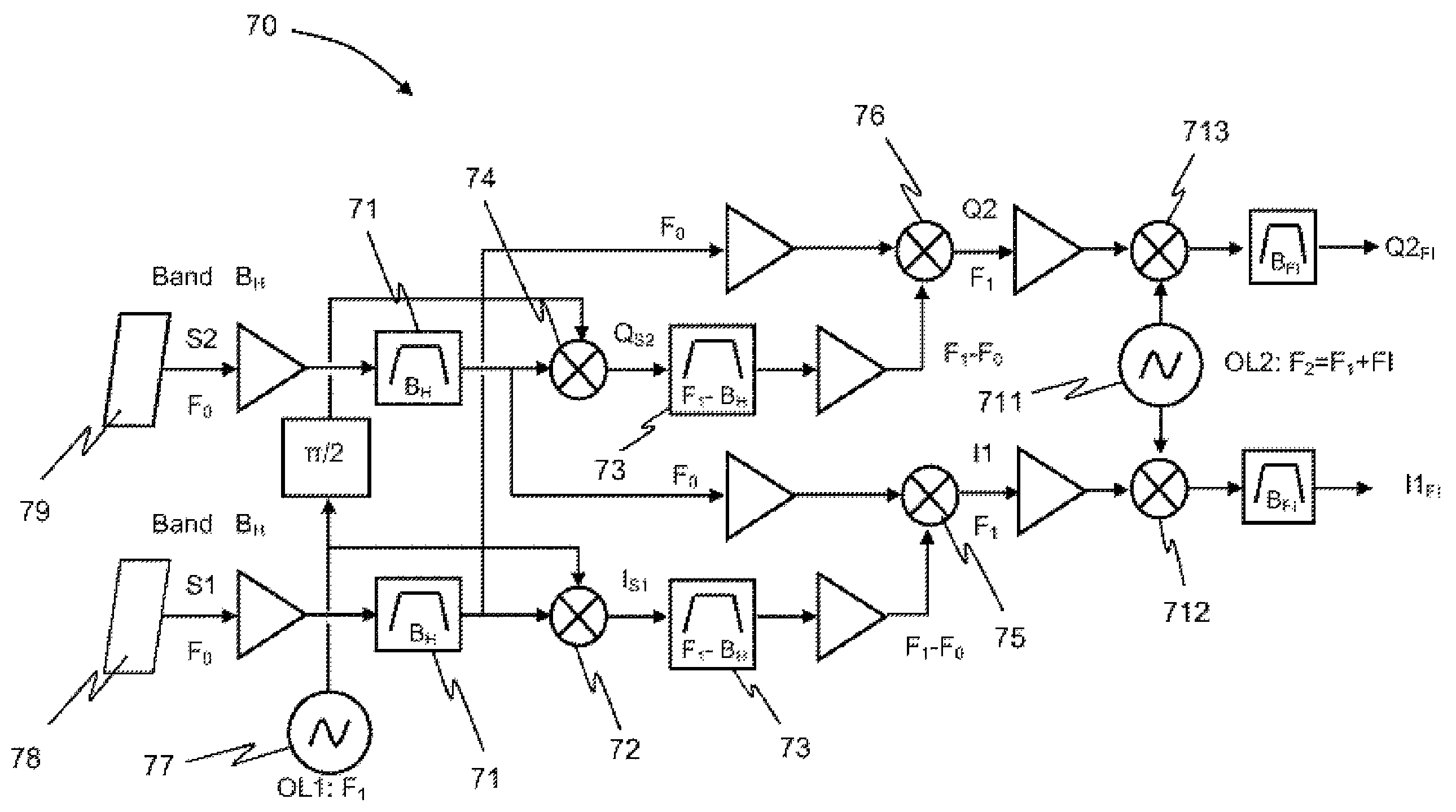
[0065]The text which follows describes the various characteristics of the device according to the invention as well as an application of this device to the production of a system ensuring the detection of emissions and the characterization of the waves constituting the detected emissions, as well as the location of the source of the detected emissions.

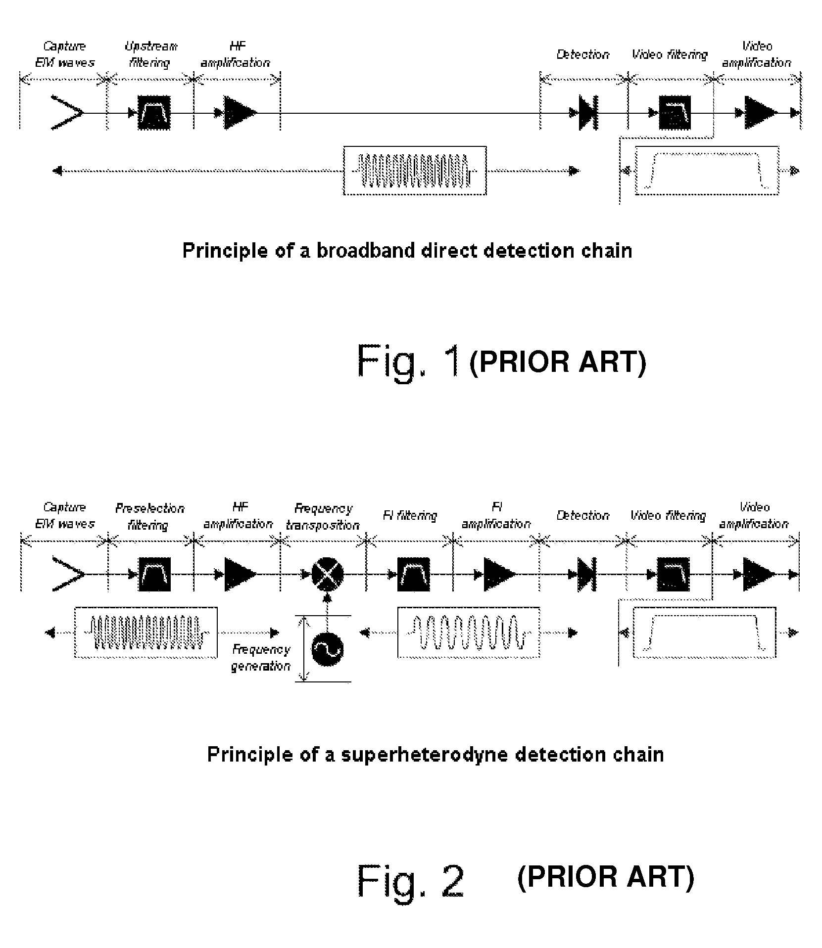
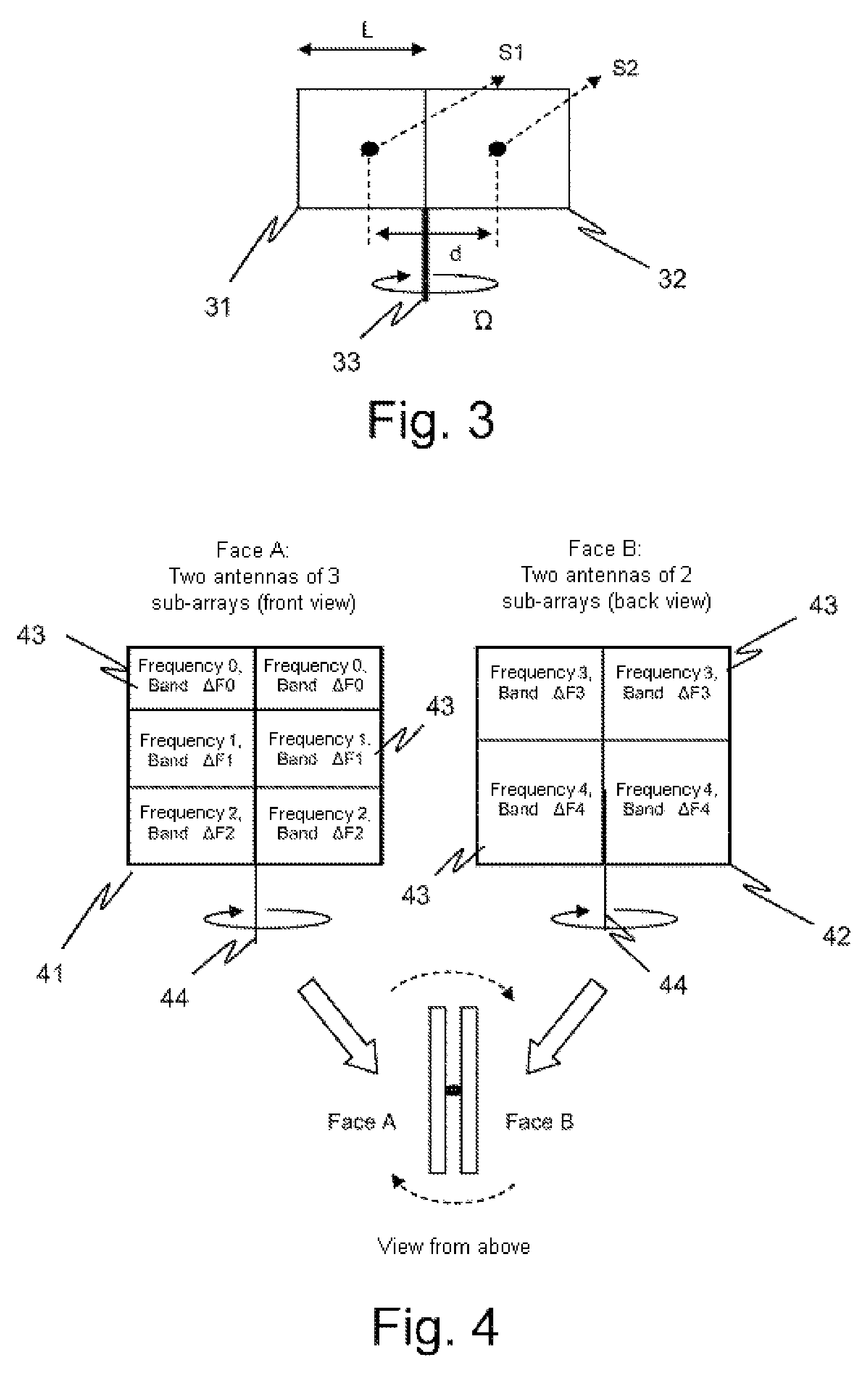
[0066]The device according to the invention comprises, in a combination, several means which cooperate to solve the problem posed, namely:[0067]At least two identical antennas, with large gain, which are directive in at least one plane, in bearing for example. These antennas are designed to simultaneously receive the signals originating from one and the same remote emitter;[0068]means forming a broadband reception chain for the signals picked up by the antennas, signals whose central frequency included in a given band BH is unknown a priori. These means are configured so as to demodulate the signal S1 picked up by the first antenna by ...


PUM


Abstract

A device is provided for use of an antennal base formed of two antennas which pick up the emissions present and produce two radioelectric signals S1 and S2. These two signals are used to produce at least one intermediate-frequency signal Fl by demodulation of one of the two signals by the other (autotransposition). The demodulation is carried out by firstly transposing one of the signals, S1 for example, around a given frequency F1, the signal S2 being preserved around its initial central frequency F0. Thus, whatever the central frequency F0 of the emission picked up by the antennas, the demodulation produces a signal of central frequency F1, thereafter demodulated into a given intermediate frequency Fl by a local oscillator of constant frequency F2=F1+Fl. The device is applied to the production of a device for detecting emissions and for characterizing the emissions picked up.

Description

CROSS-REFERENCE TO RELATED APPLICATIONS[0001]This application is a National Stage of International patent application PCT / EP2012 / 050196, filed on Jan. 6, 2012, which claims priority to foreign French patent application No. FR 1100409, filed on Feb. 10, 2011, the disclosures of which are incorporated by reference in their entirety.FIELD OF THE INVENTION[0002]The invention pertains to the general field of devices for detecting electromagnetic signals, and in particular in respect of those having a very wide expanse of emission frequencies to be received, such as for example radar detectors.BACKGROUND[0003]The operation of contemporary devices for detecting electromagnetic signals rely, in a known manner, on two different principles:[0004]Very broadband direct detection, the principle of which is illustrated by FIG. 1,[0005]Narrowband superheterodyne reception, the principle of which is illustrated by FIG. 2.[0006]Very broadband direct detection, in a band extending for example between...

Claims


Application Information

Patent Timeline
Patent Type & Authority Patents(United States)
IPC IPC(8): H01Q21/28G01S3/66H01Q25/02H01Q25/00H01Q21/20G01S3/40H01Q3/02G01S3/46H04B7/10H04B7/08
CPCH01Q25/02H04B7/08G01S3/40H01Q3/02H01Q21/20H01Q21/28G01S3/66H01Q25/004G01S3/46H01Q25/00
Inventor CORNIC, PASCALJAHAN, DANIELGARREC, PATRICK
Owner THALES SA
Why Eureka
Try Eureka