
Concurrent impedance and noise matching transconductance amplifier and receiver implementing same

a transconductance amplifier and impedance matching technology, applied in the field of electronic circuits and systems, can solve problems such as the possibility of receiving noise to be a particular source of concern, the noise of the receiver, and the flicker noise of the mixer circui

Active Publication Date: 2014-11-11
AVAGO TECH INT SALES PTE LTD
View PDF4 Cites 3 Cited by
  • Summary
  • Abstract
  • Description
  • Claims
  • Application Information

AI Technical Summary

Problems solved by technology

Because a receiver implemented in a communications transceiver may be called upon to amplify and process a weak receive signal, receiver noise may be a particular source of concern.
Receiver noise can occur in the form of front-end noise, for example, or as noise produced by the receiver matching network.
In addition, flicker noise may be produced by a mixer circuit utilized to down-convert a receive signal.
Unfortunately the presence of a large blocking capacitor may reduce the overall front-end gain of the receiver, which is an undesirable result when weak receive signals are being processed.
The problems presented by the front-end noise and matching network noise may be even more intractable, because techniques directed to achieving noise matching between the receiver front-end and the matching network for the purpose of reducing their combined noise are often at odds with achieving impedance matching between the matching network and receiver front-end.
As a result, conventional receiver designs must carefully balance the competing interests of noise matching and impedance matching when implementing a receiver, with advantageous improvements in one operating parameter typically resulting in undesirable deterioration of the other.

Method used


Image

  • Concurrent impedance and noise matching transconductance amplifier and receiver implementing same
  • Concurrent impedance and noise matching transconductance amplifier and receiver implementing same
  • Concurrent impedance and noise matching transconductance amplifier and receiver implementing same

Examples


Embodiment Construction

[0013]The present invention is directed to a concurrent impedance and noise matching transconductance amplifier and receiver implementing same. Although the invention is described with respect to specific embodiments, the principles of the invention, as defined by the claims appended herein, can obviously be applied beyond the specifically described embodiments of the invention described herein. Moreover, in the description of the present invention, certain details have been left out in order to not obscure the inventive aspects of the invention. The details left out are within the knowledge of a person of ordinary skill in the art.

[0014]The drawings in the present application and their accompanying detailed description are directed to merely exemplary embodiments of the invention. To maintain brevity, other embodiments of the invention, which use the principles of the present invention are not specifically described in the present application and are not specifically illustrated by...


PUM


Abstract

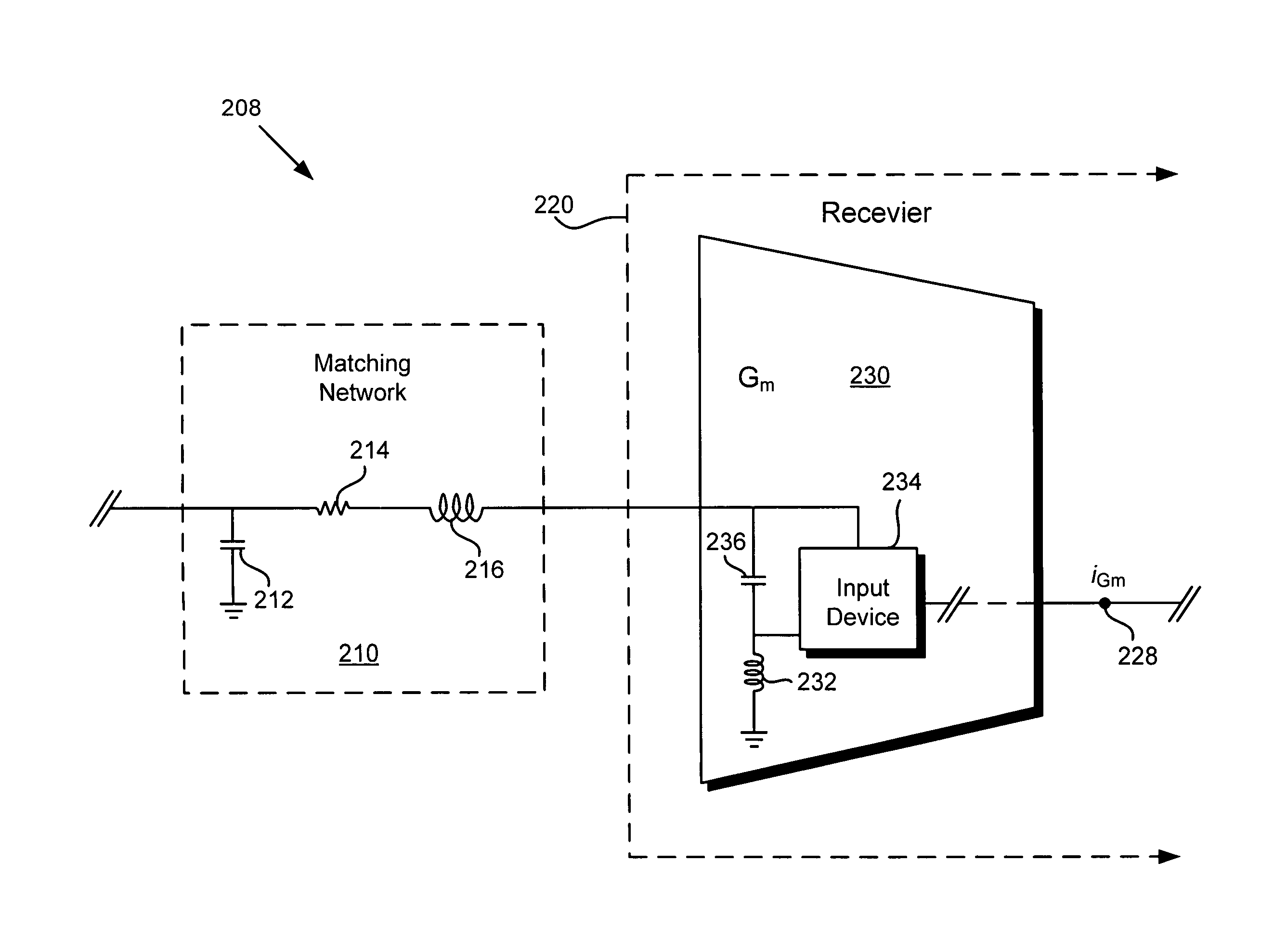
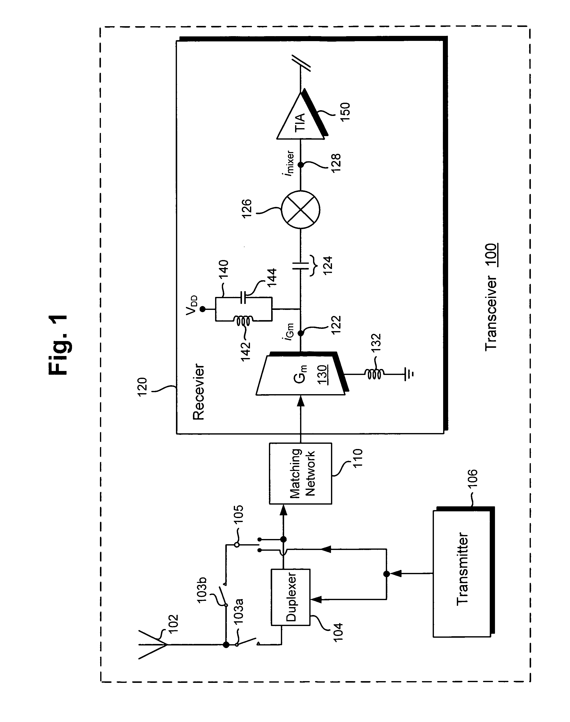
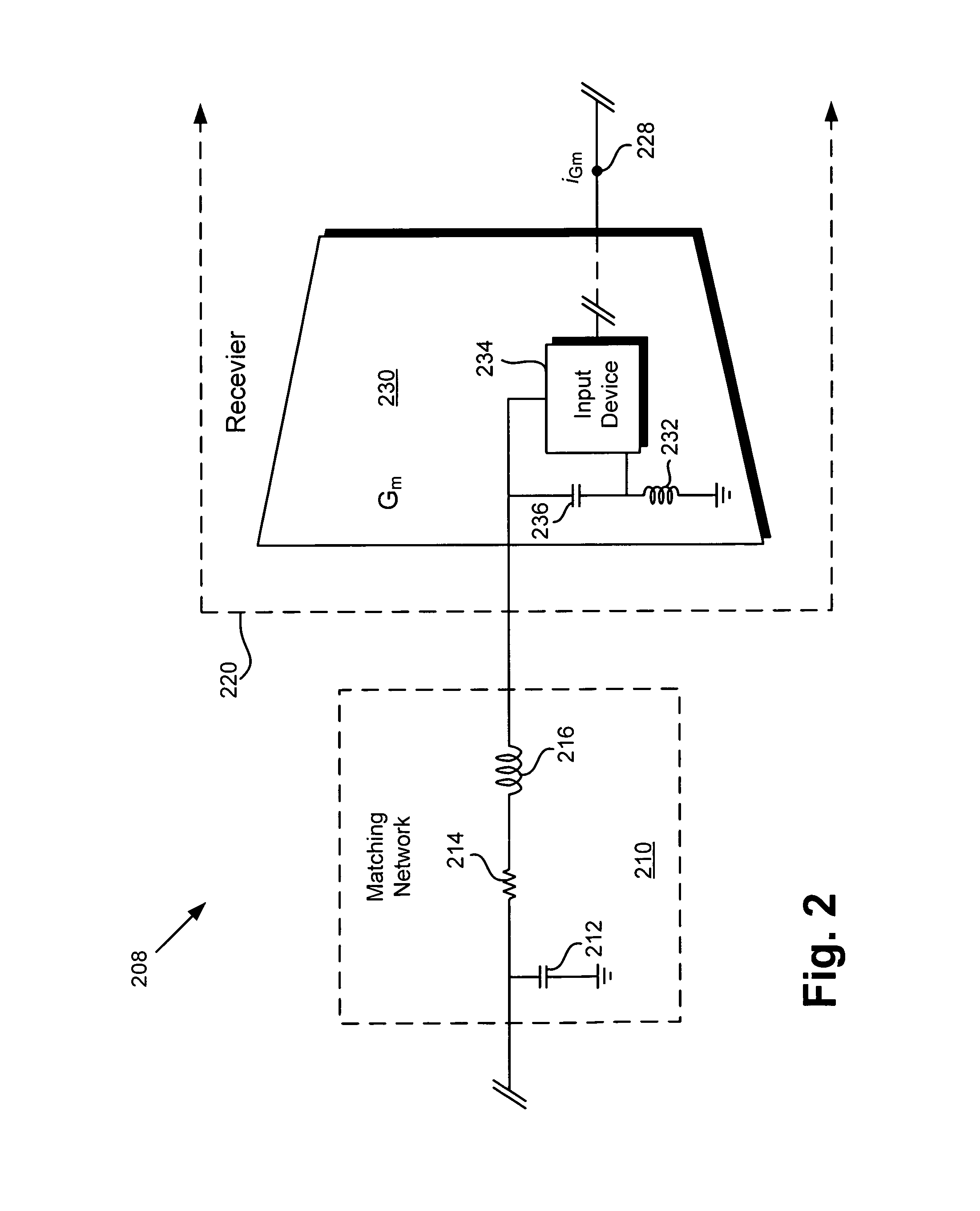
According to one embodiment, a concurrent impedance and noise matching transconductance amplifier designed for implementation in a receiver comprises an input device configured to couple to a matching network of the receiver, and a boost capacitor connected to the input device to increase an input capacitance of the transconductance amplifier. The boost capacitor is selected to substantially minimize the receiver noise and to enable the concurrent impedance and noise matching of the receiver and the matching network. In one embodiment, the receiver comprises the transconductance amplifier to provide an amplified receive signal, and a mixer to produce a down-converted signal corresponding to the amplified receive signal, wherein the mixer is coupled to the transconductance amplifier by a blocking capacitor. The blocking capacitor is selected to substantially increase an amplitude ratio of the down-converted signal to the amplified receive signal to substantially increase the front-end gain of the receiver.

Description

BACKGROUND OF THE INVENTION[0001]1. Field of the Invention[0002]The present invention is generally in the field of electronic circuits and systems. More specifically, the present invention is in the field of communications circuits and systems.[0003]2. Background Art[0004]Transceivers are typically used in communications systems to support transmission and reception of communications signals through a common antenna, for example, at radio frequency (RF) in a cellular telephone or other mobile communication device. Because a receiver implemented in a communications transceiver may be called upon to amplify and process a weak receive signal, receiver noise may be a particular source of concern. Receiver noise can occur in the form of front-end noise, for example, or as noise produced by the receiver matching network. In addition, flicker noise may be produced by a mixer circuit utilized to down-convert a receive signal.[0005]In a conventional receiver, the problem of flicker noise may...

Claims


Application Information

Patent Timeline
Patent Type & Authority Patents(United States)
IPC IPC(8): H04B1/16H03F1/56H03F3/193H03F1/22H04B1/18
CPCH04B1/18H03F1/223H03F2200/294H03F1/565H03F3/193H03F2200/222
Inventor MIKHEMAR, MOHYEEDARABI, HOOMAN
Owner AVAGO TECH INT SALES PTE LTD
Learn More