Inductively coupled plasma arc device

a plasma arc and inductive coupling technology, applied in the field of plasma torches, can solve the problems of one fluid exit one fluid complexity, etc., and achieve the effect of reducing the complexity of gas regulation, less complex, and low cos

Active Publication Date: 2014-12-09
FORET PLASMA LABS
View PDF84 Cites 36 Cited by
  • Summary
  • Abstract
  • Description
  • Claims
  • Application Information

AI Technical Summary

Benefits of technology

[0006]The present invention provides an inductively coupled plasma device that is less complex, lower in cost and more efficient that current systems in order for plasma to be accepted as a mainstream device for use in the aforementioned applications and processes. The devices described herein reduce the complexity of gas regulation (upstream and downstream fluid flow), current control, voltage control, plasma ignition, sustainment and confinement by using a moveable electrode in combination with an electrode nozzle, a tangential entry and exit, and a wave energy source selected from electromagnetic radiation (“EMR”) within the radio frequency (“RF”) range all the way to a line frequency of 50 or 60 Hz. As a result, the present invention opens the door for wide scale use of plasma for heavy industrial applications as well as commercial, residential and transportation applications.

Problems solved by technology

One of the major drawbacks for using plasma for other applications is the complexity and cost of existing systems.
As a result, current plasma systems are not widely used for steam reforming, cracking, gasification, partial oxidation, pyrolysis, heating, melting, sintering, rich combustion and / or lean combustion.
The major unresolved issue with current commercially available plasma torches that use inertia confinement is that there is only one fluid exit—through the nozzle—for confining the plasma.
These problems have plagued the plasma industry and thus plasma torches are viewed as difficult to operate due to the power supplies, controls, gases and valves associated with the torches.

Method used


Image

  • Inductively coupled plasma arc device
  • Inductively coupled plasma arc device
  • Inductively coupled plasma arc device

Examples


Embodiment Construction

[0031]While the making and using of various embodiments of the present invention are discussed in detail below, it should be appreciated that the present invention provides many applicable inventive concepts that can be embodied in a wide variety of specific contexts. The specific embodiments discussed herein are merely illustrative of specific ways to make and use the invention and do not delimit the scope of the invention.

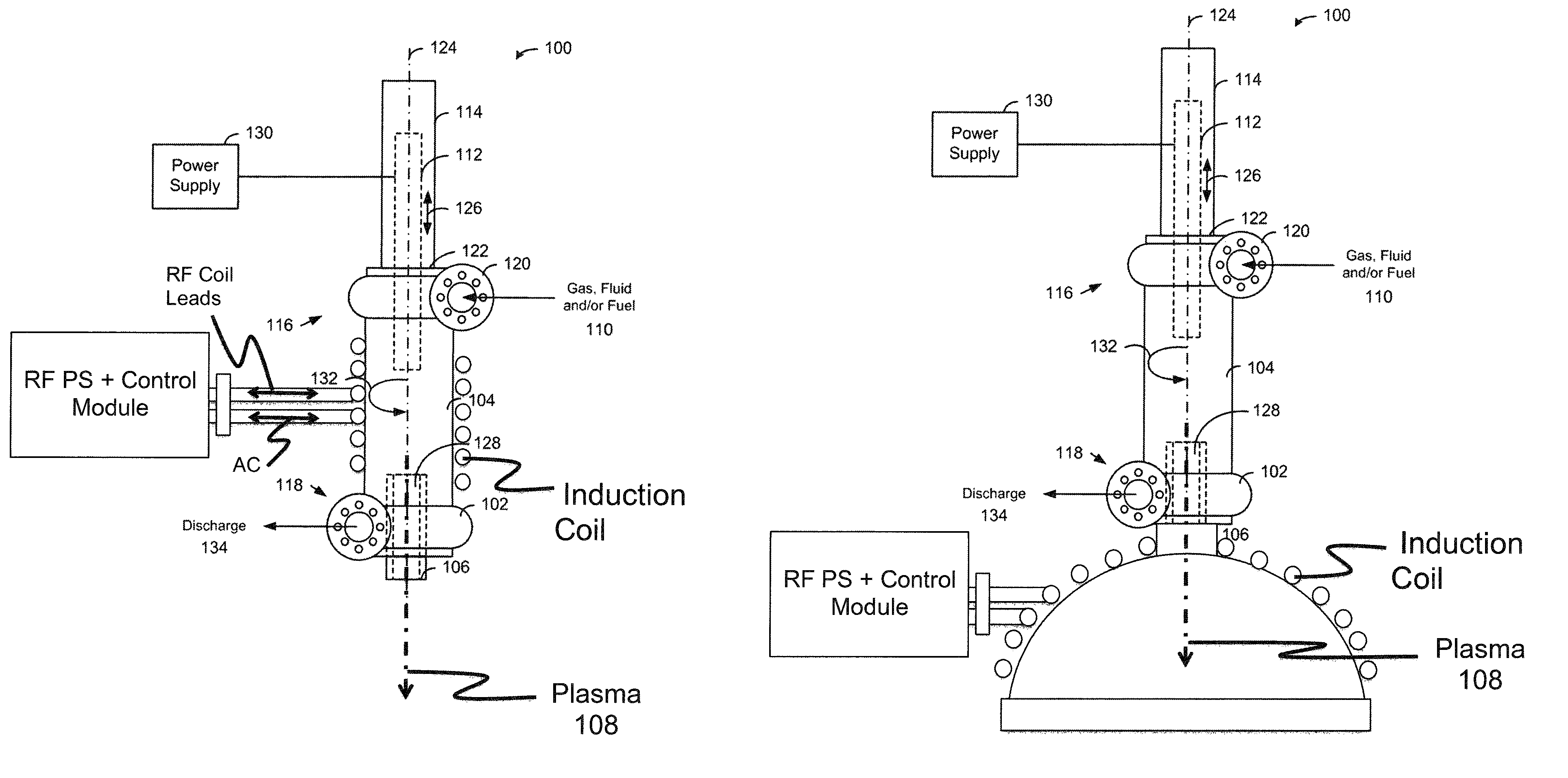
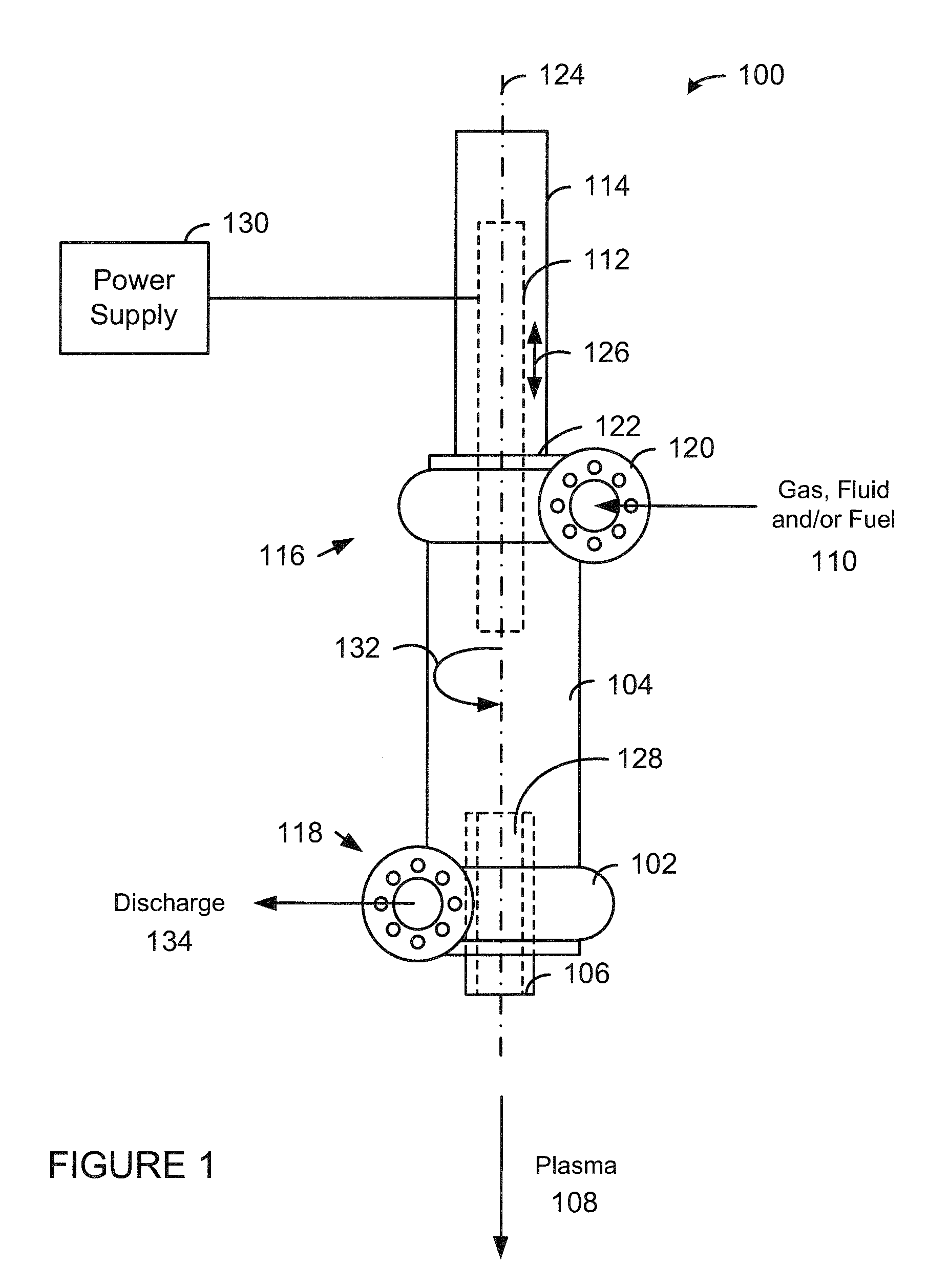
[0032]Now referring to FIG. 1, a plasma arc torch 100 in accordance with one embodiment of the present invention is shown. The plasma arc torch 100 is a modified version of the ARCWHIRL® device disclosed in U.S. Pat. No. 7,422,695 (which is hereby incorporated by reference in its entirety) that produces unexpected results. More specifically, by attaching a discharge volute 102 to the bottom of the vessel 104, closing off the vortex finder, replacing the bottom electrode with a hollow electrode nozzle 106, an electrical arc can be maintained while discharging plas...


PUM

PropertyMeasurementUnit
frequencyaaaaaaaaaa
frequencyaaaaaaaaaa
temperaturesaaaaaaaaaa

Abstract

The present invention provides an inductively coupled plasma device with a cylindrical vessel having a first end and a second end, wherein at least a portion of the cylindrical vessel is transparent or semi-transparent to a wave energy. A tangential inlet is connected to or proximate to the first end. A tangential outlet is connected to or proximate to the second end. An electrode housing is connected to the first end of the cylindrical vessel such that a first electrode is (a) aligned with a longitudinal axis of the cylindrical vessel, and (b) extends into the cylindrical vessel. A hollow electrode nozzle is connected to the second end of the cylindrical vessel such that the center line of the hollow electrode nozzle is aligned with the longitudinal axis of the cylindrical vessel. An electromagnetic radiation source that produces a wave energy and is disposed around or within the cylindrical vessel.

Description

PRIORITY CLAIM[0001]This patent application is a continuation-in-part patent application of U.S. patent application Ser. No. 12 / 370,591 filed on Feb. 12, 2009 and entitled “System, Method and Apparatus for Lean Combustion with Plasma from an Electrical Arc,” which is a non-provisional patent application of U.S. provisional patent application Ser. No. 61 / 027,879 filed on Feb. 12, 2008 and entitled, “System, Method and Apparatus for Lean Combustion with Plasma from an Electrical Arc,” both of which are hereby incorporated by reference in their entirety.FIELD OF THE INVENTION[0002]The present invention relates generally to plasma torches. More specifically, the present invention relates to inductively coupled plasma arc devices.BACKGROUND OF THE INVENTION[0003]Plasma is primarily used for cutting metal, plasma spraying, analysis of gases via IC Mass Spectrometry, plasma TVs, plasma lighting and expensive production of nanopowders. One of the major drawbacks for using plasma for other a...

Claims


Application Information

Patent Timeline
Patent Type & Authority Patents(United States)
IPC IPC(8): F02C7/266F03H1/00F02C3/14H05H1/32H05H1/42H05H1/30H05H1/34
CPCH05H2001/3426H05H1/32H05H2001/3489F02C7/266F23R2900/00009F02C3/14H05H1/42H05H1/30Y02T50/678F23R2900/00002Y02E50/12H05H1/34H05B6/02H05B7/20F27B3/085H05H1/3421H05H1/3489Y02E50/10
Inventor FORET, TODD
Owner FORET PLASMA LABS
Why Eureka
Try Eureka