Delay difference detection and adjustment device and method

a technology of delay difference and adjustment device, which is applied in the direction of pulse automatic control, electrical apparatus, pulse shaping, etc., can solve the problems of malfunction of synchronous circuit, ineffective resolution, and worse clock skew

Active Publication Date: 2014-12-09
REALTEK SEMICON CORP
View PDF11 Cites 2 Cited by
  • Summary
  • Abstract
  • Description
  • Claims
  • Application Information

AI Technical Summary

Benefits of technology

[0007]In consideration of the problems of the prior arts, an object of the present invention is to provide a delay difference detection and adjustment device and method capable of detecting and adjusting a delay difference between two delay circuits, so as to improve the prior arts.
[0008]Another object of the present invention is to provide the aforementioned delay difference detection and adjustment device and method, so as to raise the accuracy / precision of clock detection.

Problems solved by technology

This problem is called clock skew, and a serious one will probably cause a malfunction of the synchronous circuit.
As semiconductor process development moves on and the process variation thereof becomes significant, the problem of clock skew is getting worse.
However, if the design requirement of said solution is too loose, the problem of clock skew can't be resolved effectively; on the contrary, if the design requirement is too strict, it will be a waste of the design resource.
Unfortunately, under the limitation of element precision (e.g. the minimal delay amount of a delay element), the current clock skew detection techniques are merely able to measure the deviation of a clock roughly.

Method used


Image

  • Delay difference detection and adjustment device and method
  • Delay difference detection and adjustment device and method
  • Delay difference detection and adjustment device and method

Examples


Embodiment Construction

[0014]The following description is written by referring to terms of this invention field. If any term is defined in the specification, such term should be explained accordingly. Besides, the connection between objects or events in the disclosed embodiments can be direct or indirect provided that these embodiments are still applicable under such connection. Said “indirect” means that an intermediate object or a physical space is existed between the objects, or an intermediate event or a time interval is existed between the events. In addition, the following description relates to delay detection and adjustment technology, and the common knowledge known in this field will be omitted if such knowledge has little to do with the features of the present invention. Furthermore, the shape, size, and ratio of any element and the step sequence of any flow chart in the disclosed figures are just exemplary for understanding, not for limiting the scope of this invention.

[0015]The present inventi...


PUM


Abstract

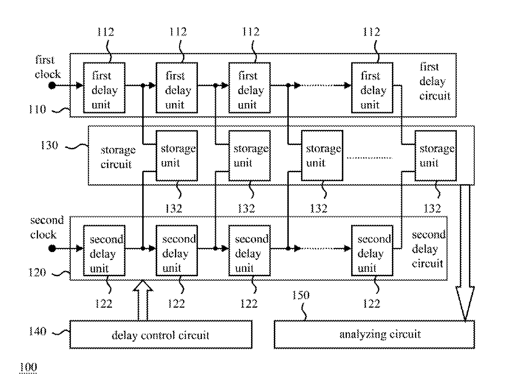
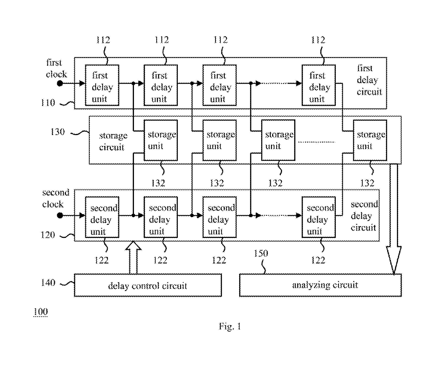
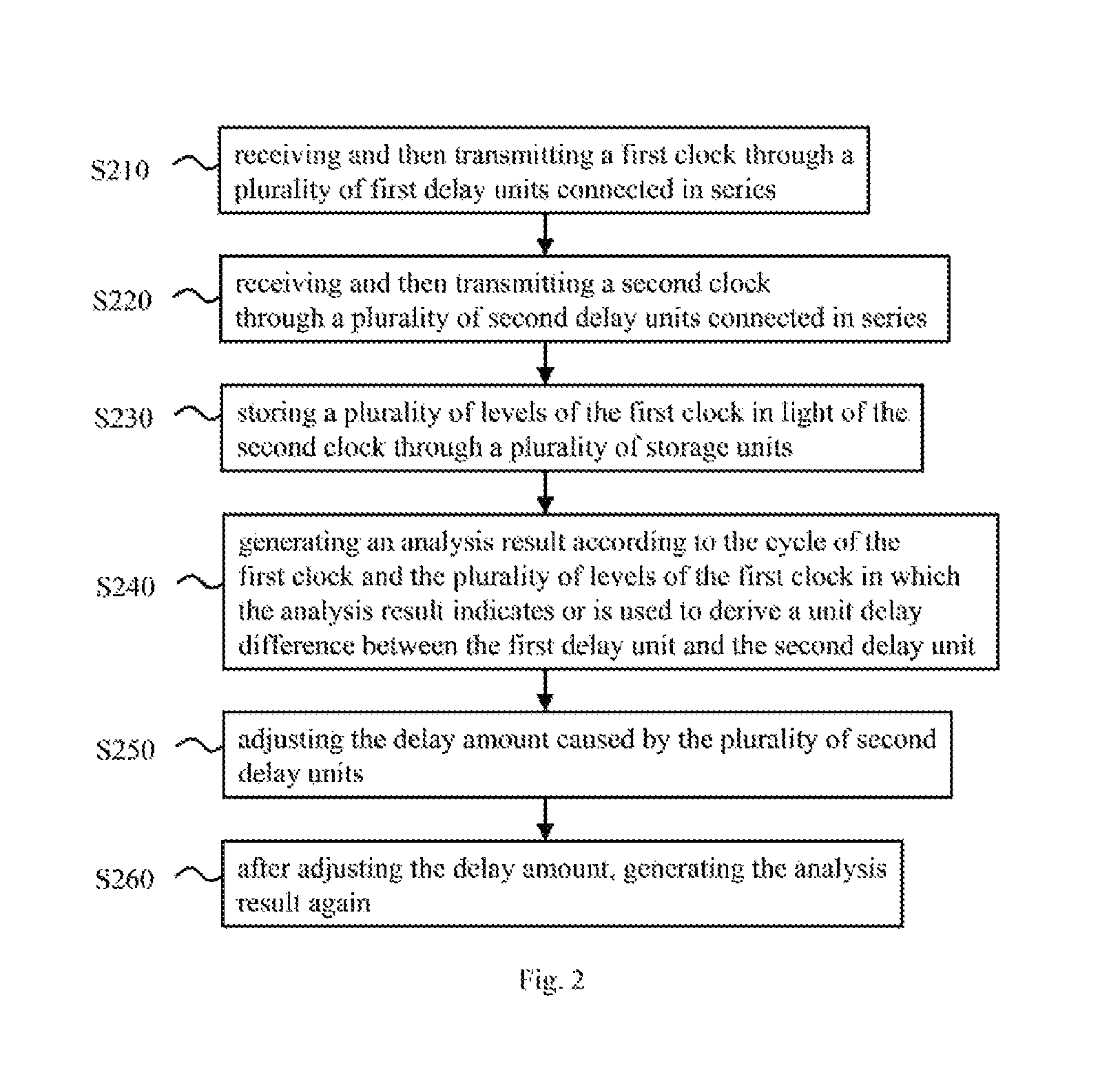
The present invention discloses a delay difference detection and adjustment device comprising: a first delay circuit including first delay units to receive and transmit a first clock; a second delay circuit including second delay units to receive and transmit a second clock; a storage circuit including storage units, each of which includes a data input end to receive the first clock and an operation clock reception end to receive the second clock, so that the storage circuit is operable to save a plurality of levels of the first clock according to the second clock; a delay control circuit to adjust the delay amount of the second delay circuit; and an analyzing circuit to generate an analysis result according to the cycle and levels of the first clock in which the analysis result indicates or is used to derive a unit delay difference between the first and second delay units.

Description

BACKGROUND OF THE INVENTION[0001]1. Field of the Invention[0002]The present invention relates to a detection and adjustment device and method, especially to a delay difference detection and adjustment device and method.[0003]2. Description of Related Art[0004]In a synchronous circuit, a common reference clock is necessary for different components to operate synchronously. The common reference clock is usually generated by a frequency synthesizer in accordance with a source clock. However, because the paths from the frequency synthesizer to the different components are not the same, deviations (a.k.a. time difference or phase difference) may exist among the reference clocks received by the components. This problem is called clock skew, and a serious one will probably cause a malfunction of the synchronous circuit.[0005]As semiconductor process development moves on and the process variation thereof becomes significant, the problem of clock skew is getting worse. Some solution is reali...

Claims


Application Information

Patent Timeline
Patent Type & Authority Patents(United States)
IPC IPC(8): H03K5/06H03L7/00
CPCH03K5/06
Inventor LO, YU-CHENGCHEN, YING-YENTZENG, CHAO-WENLEE, JIH-NUNG
Owner REALTEK SEMICON CORP
Why Eureka
Try Eureka