Chromatic dispersion pre-compensation

Active Publication Date: 2014-12-09
MACOM CONNECTIVITY SOLUTIONS LLC
View PDF6 Cites 28 Cited by
  • Summary
  • Abstract
  • Description
  • Claims
  • Application Information

AI Technical Summary

Problems solved by technology

However, dispersion also has an effect in many other circumstances: for example, GVD causes pulses to spread in optical fibers, degrading signals over long distances; also, a cancellation between group-velocity dispersion and nonlinear effects leads to soliton waves.
For example, material dispersion leads to undesired chromatic aberration in a lens or the separation of colors in a prism.
Their combination leads to signal degradation in optical fibers for telecommunications, because the varying delay in arrival time between different components of a signal “smears out” the signal in time.
When the dispersion is anomalous, however, group velocity is no longer an indicator of signal velocity.
One possible answer to this problem is to send signals down the optical fiber at a wavelength where the GVD is zero (e.g., around 1.3-1.5 μm in silica fibers), so pulses at this wavelength suffer minimal spreading from dispersion—in practice, however, this approach ca

Method used


Image

  • Chromatic dispersion pre-compensation
  • Chromatic dispersion pre-compensation
  • Chromatic dispersion pre-compensation

Examples


Embodiment Construction

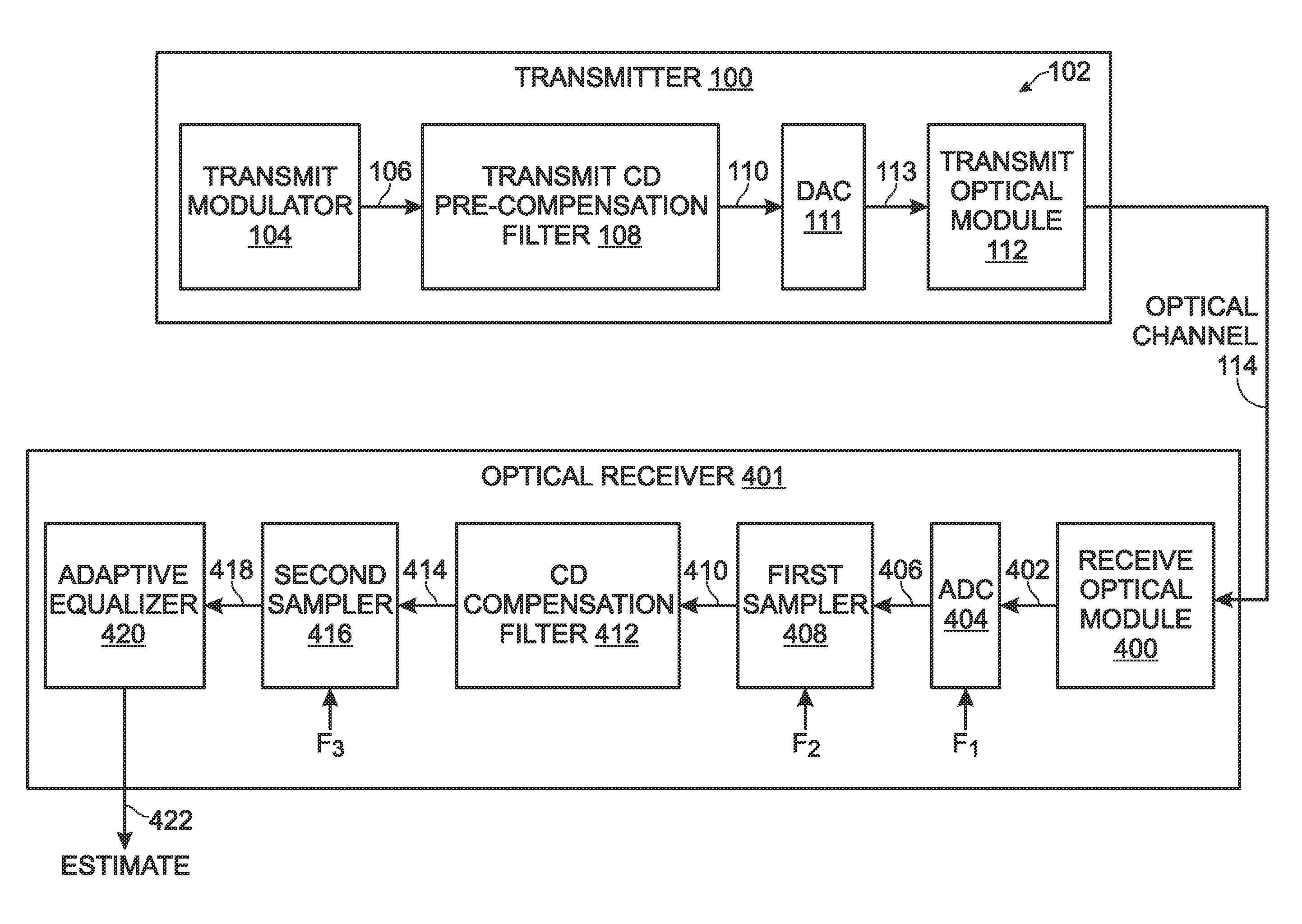
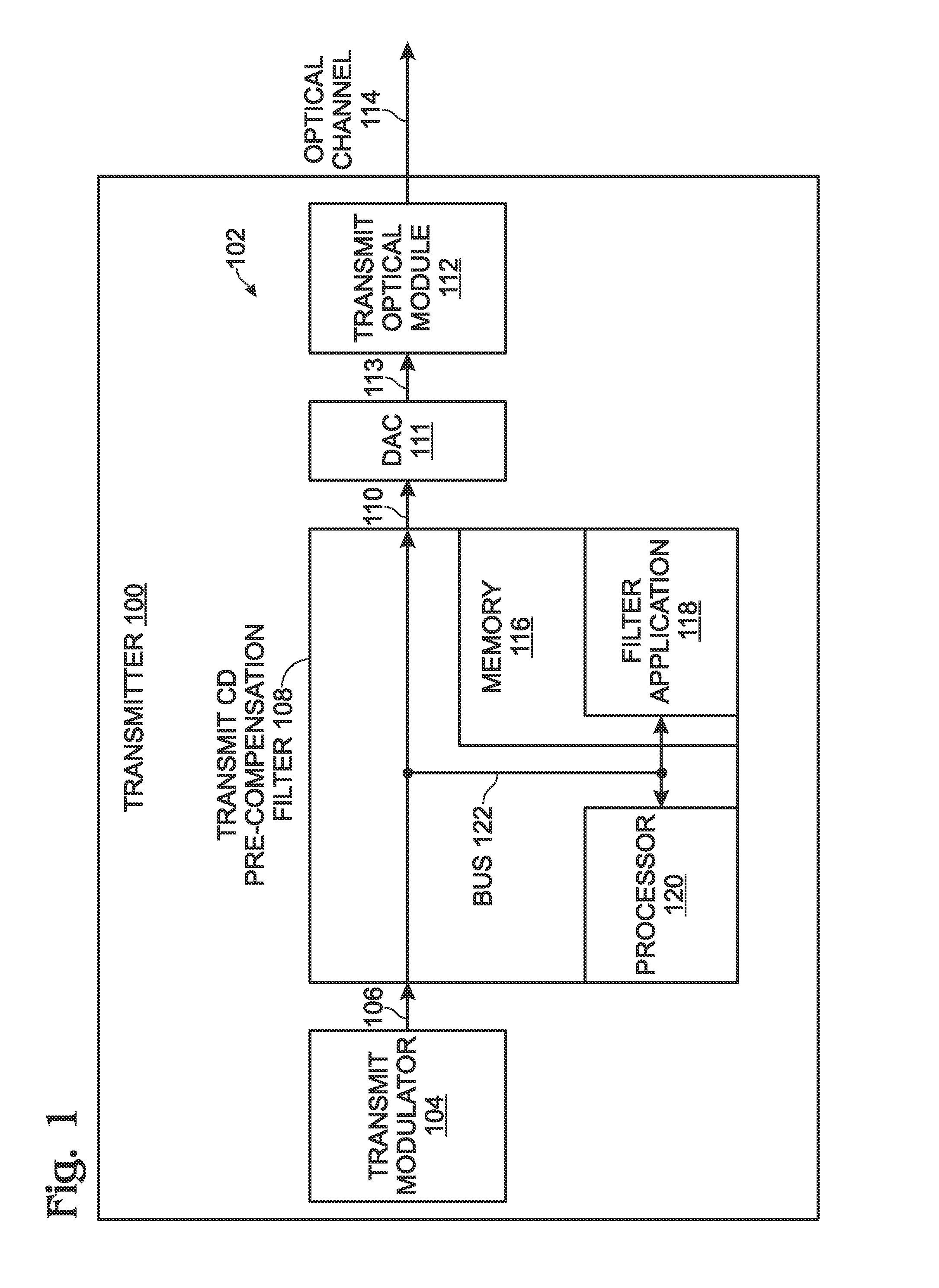
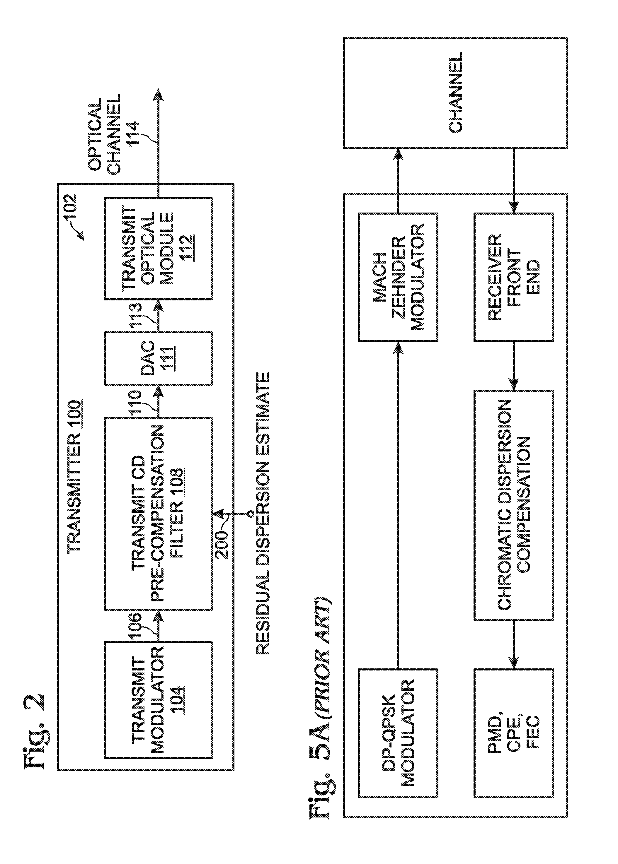
[0057]FIG. 1 is a schematic block diagram of a first optical transmitter 100 with a system for performing chromatic dispersion (CD) pre-compensation. The system 102 comprises a transmit modulator 104 having an output on line 106 to supply a first electronic signal. A transmit CD pre-compensation filter 108, built from a CD compensation estimate, has an input on line 106 to accept the first electronic signal. The transmit CD pre-compensation filter 108 processes the first electronic signal and supplies a pre-compensated first electronic signal at an output on line 110. A transmit optical module 112 has an input to accept the pre-compensated first electronic signal and an output for transmitting the optical signal to a first optical receiver (not shown) via an optical channel 114. In one aspect, the transmit optical module 112 is a Mach-Zehnder modulator, and a digital-to-analog converter 111 (DAC) is interposed between the transmit CD pre-compensation filter 108 and the Mach Zehnder ...


PUM


Abstract

A method is provided for performing chromatic dispersion (CD) pre-compensation. The method generates an electronic signal at a transmitter, and uses a transmit CD compensation estimate to compute a CD pre-compensation filter. The transmit CD pre-compensation filter is used to process the electronic signal, generating a pre-compensated electronic signal. The pre-compensated electronic signal is converted into an optical signal and transmitted to an optical receiver via an optical channel. In one aspect, the transmitter generates a test electronic signal and the CD compensation estimate uses a first dispersion value to compute a first CD compensation filter. The transmitter accepts a residual dispersion estimate of the test optical signal from the first optical receiver CD compensation filter, generated from a (receiver-side) CD estimate, and then the transmit CD estimate can be modified in response to the combination of the first dispersion value and residual dispersion estimate.

Description

RELATED APPLICATIONS[0001]This application is a Continuation-in-Part of a pending application entitled, OPTIMIZED CHROMATIC DISPERSION FILTER, invented by Badri Varadarajan et al., Ser. No. 13 / 413,705, filed Mar. 7, 2012, which is incorporated herein by reference.BACKGROUND OF THE INVENTION[0002]1. Field of the Invention[0003]This invention generally relates to optical communications and, more particularly, to a transmitter filter that pre-compensates for the effects of chromatic dispersion in an optical communications channel.[0004]2. Description of the Related Art[0005]Wikipedia notes that in optics, dispersion is the phenomenon in which the phase velocity of a wave depends on its frequency, or alternatively when the group velocity depends on the frequency. Media having such a property are termed dispersive media. Dispersion is sometimes called chromatic dispersion to emphasize its wavelength-dependent nature, or group-velocity dispersion (GVD) to emphasize the role of the group v...

Claims


Application Information

Patent Timeline
IPC IPC(8): H04B10/00
CPCH04B10/6161H04B10/0775H04B10/25137
Inventor VARADARAJAN, BADRI
Owner MACOM CONNECTIVITY SOLUTIONS LLC
Why Eureka
Try Eureka