Miniature sieve apparatus and manufacturing method thereof

a technology of miniature sieve and manufacturing method, which is applied in the direction of separation process, instruments, laboratory glassware, etc., can solve the problems of not only complicated and difficult to execute mems processes, but also significant difficulties in the whole manufacturing process of traditional sieve apparatus, etc., and achieve the effect of enhancing the structural stability of the miniature sieve apparatus

Inactive Publication Date: 2014-12-16
NAT APPLIED RES LAB
View PDF9 Cites 3 Cited by
  • Summary
  • Abstract
  • Description
  • Claims
  • Application Information

AI Technical Summary

Benefits of technology

[0010]A primary object of the present invention is to provide a miniature sieve apparatus, wherein the same material (such as silicon substrate) is used to manufacture a first and a second sieve, and a separator is disposed between the first and second sieves, wherein the material of the separator can be made of the same or different material of the first and second sieves. Because it is unnecessary for the above-mentioned process to use coating steps, the problems of generating residual stress and stress distribution in the traditional three-dimensional sieve can be improved, and the structural stability of the miniature sieve apparatus can be enhanced.
[0011]A secondary object of the present invention is to provide a manufacturing method of a miniature sieve apparatus, wherein material of a sacrificial layer is not used between the first and second sieves, and the first and second sieves can be formed with a first and a plurality of second meshes by etching, respectively. Therefore, it is simple to precisely control the mesh size of the sieves. Further, when manufacturing another miniature sieve apparatus of different specification for screening different targets, it only needs to change new first sieve with different mesh size, so that the design flexibility can be increased, the manufacture process can be simplified, and the manufacture efficiency of the miniature sieve apparatus can be enhanced.
[0016]In one embodiment of the present invention, the material of the separator is selected from the same material of the first and second sieves. Thus, during assembling, the miniature sieve apparatus can provide the same coefficient of thermal expansion (CTE) for maintaining planarity after assembling and enhancing the fabrication yield.
[0021]According to the design concept of the present invention, when the to-be-sieved targets are changed, it only needs to change new first sieve with different mesh size, so as to construct a new miniature sieve having corresponding specification after heating assembly. Therefore, the manufacturing processes of the miniature sieve apparatus can be simplified and the cost thereof can be lowered, while the industrial requirement of re-design flexibility can be satisfied. Furthermore, the diversity of the miniature sieve apparatus can be increased to meet needs of the market.

Problems solved by technology

However, no matter for modifying the surface of the magnetic particles or conjugating the magnetic particles to the specific protein, the particular magnetic particles must be added during screening different target cells, so that the cost of detection will be increased.
Moreover, it also needs to consider the three materials of the 3D sieve apparatus with the problems of residual stress generated during the manufacture process and to consider relative parameters thereof, so that it is significantly difficult in the whole manufacturing process of the 3D sieve apparatus.
As a result, the traditional sieve apparatus manufactured, by the MEMS technology is not only complicated and difficult to execute MEMS processes, but also the stability of the manufacture yield thereof is still not good.
Therefore, it is difficult to lower the manufacture cost of industrial mass production.

Method used


Image

  • Miniature sieve apparatus and manufacturing method thereof
  • Miniature sieve apparatus and manufacturing method thereof
  • Miniature sieve apparatus and manufacturing method thereof

Examples


Embodiment Construction

[0034]The structure and the technical means adopted by the present invention to achieve the above and other objects can be best understood by referring to the following detailed description of the preferred embodiments and the accompanying drawings. Furthermore, directional terms described by the present invention, such as upper, lower, front, back, left, right, inner, outer, side, longitudinal / vertical, transverse / horizontal, and etc., are only directions by referring to the accompanying drawings, and thus the used directional terms are used to describe and understand the present invention, but the present invention is not limited thereto.

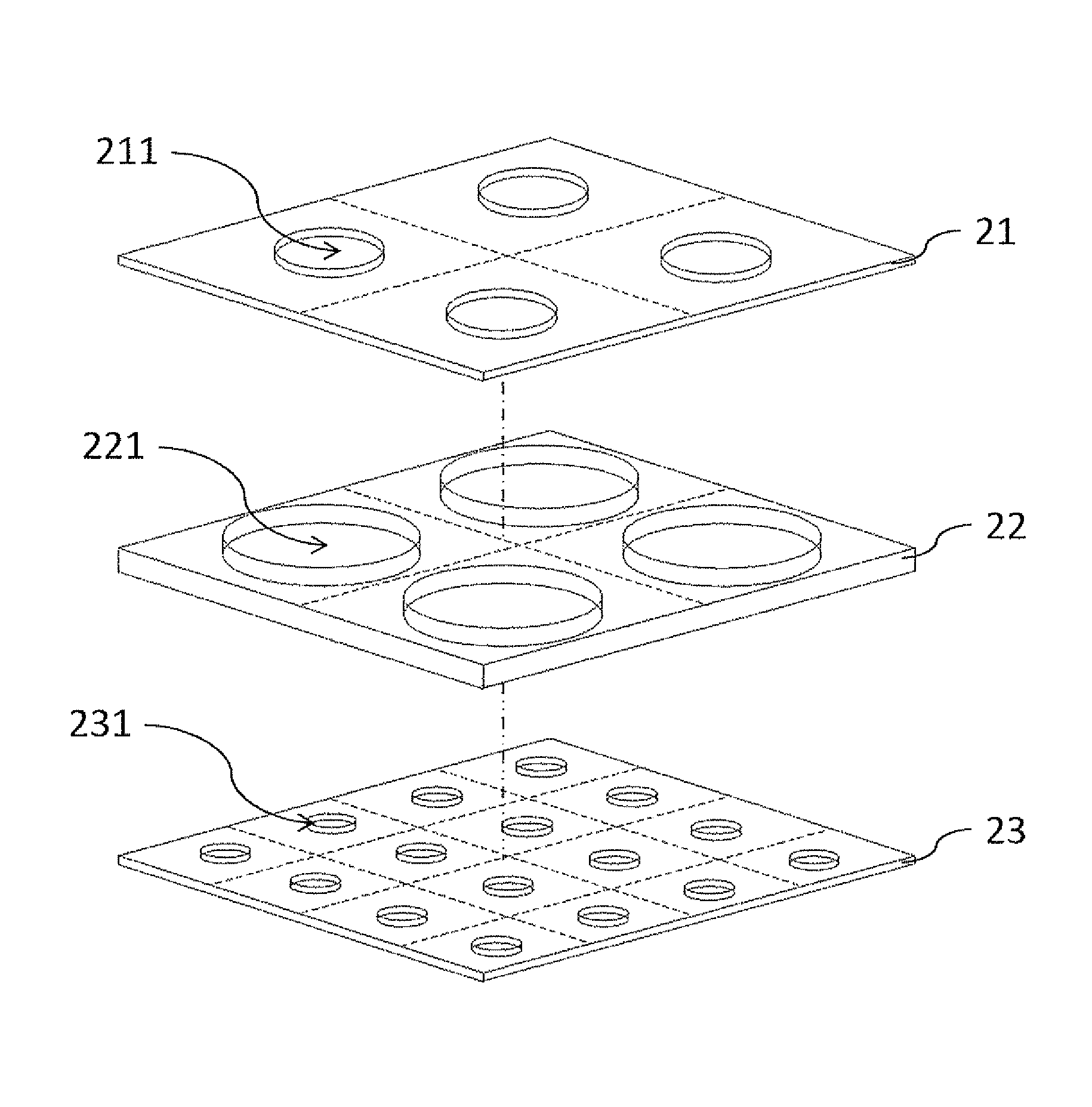
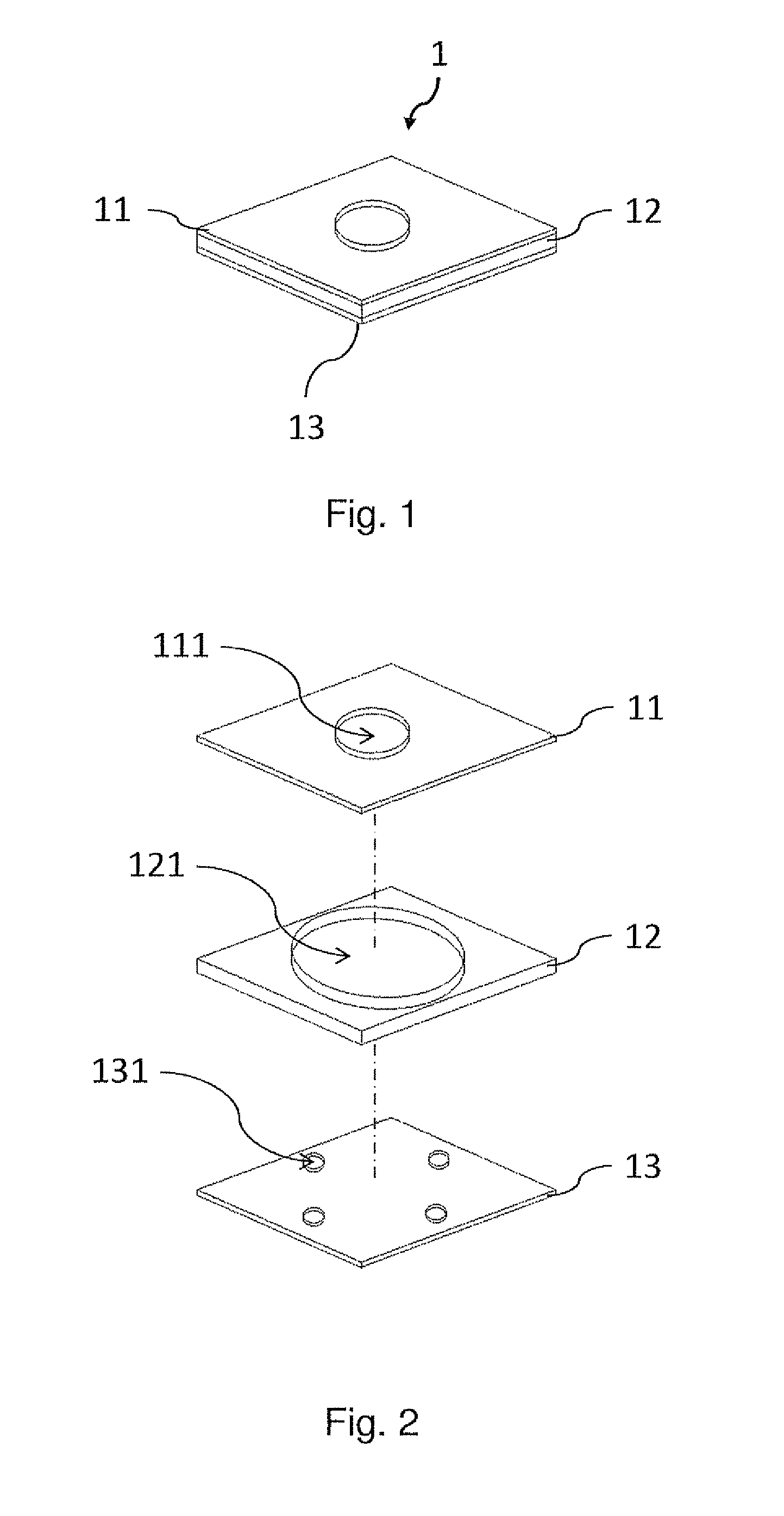
[0035]Referring now to FIGS. 1 and 2, a miniature sieve apparatus according to a first embodiment of the present invention is illustrated. As shown, the miniature sieve designated by numeral 1 comprises at least one sieve unit 1 and each of the sieve unit 1 comprises a first sieve 11, a separator 12 and a second sieve 13. The first sieve ills form...


PUM

PropertyMeasurementUnit
conductivityaaaaaaaaaa
diameteraaaaaaaaaa

Abstract

A miniature sieve apparatus is described and includes a first sieve, a separator and a second sieve from top to bottom. The first and second sieves are formed with at least one first mesh and a plurality of second meshes, respectively. The first and second meshes are misaligned with each other in a vertical direction of the first and second sieves. The miniature sieve apparatus is provided to separate or screen microparticles with different sizes, such as target cells, bio-medical particles, organic or inorganic microparticles. Additionally, the invention also provides a manufacturing method of the miniature sieve apparatus, and the same material is applied to manufacture the sieves and the separators. Thus, the problem caused by the residual thermal stress due to different material can be solved. Therefore, the cost of the miniature sieve apparatus can be lowered as the yield rate thereof is improved.

Description

FIELD OF THE INVENTION[0001]The present invention relates to a miniature sieve apparatus and a manufacturing method thereof, and more particularly to a miniature sieve apparatus for separating target cells, bio-medical particles, organic or inorganic microparticles with different sizes and a manufacturing method thereof.BACKGROUND OF THE INVENTION[0002]Traditionally, cell separation technologies include active and passive cell separation technologies, wherein the active cell separation technology means that the target cells are filtrated or separated by different approaches, such as dielectrophoresis, optical tweezers, and magnetic force. Furthermore, most of the passive cell separation technologies mean that the target cells are filtrated or separated by sieve elements, and the size of meshes on sieves can prevent target cells from passing through the sieves.[0003]For example, referring now to Taiwan Pat. No. I308131, a bio-particle capturing apparatus having a 3D structure and a m...

Claims


Application Information

Patent Timeline
Patent Type & Authority Patents(United States)
IPC IPC(8): B01D29/07B01D41/00B01D35/00
CPCB01L2200/0668G01N15/0272B01L2300/0893B01L3/50255B01L2300/0819B01L2300/0681B01L2400/049Y10T29/49885
Inventor HUANG, CHUN-MINGCHEN, CHEN-CHIALIN, CHI-SHENGWU, CHIEN-MING
Owner NAT APPLIED RES LAB
Why Eureka
Try Eureka