
Threaded thin-walled drill tube joint

a thin-walled drill tube and threaded joint technology, which is applied in the direction of hose connection, screw threaded joint, mechanical apparatus, etc., can solve the problem of difficult manufacturing of tube joints, and achieve the effect of easy manufacturing

Active Publication Date: 2014-12-30
SANDVIK INTELLECTUAL PROPERTY AB
View PDF8 Cites 4 Cited by
  • Summary
  • Abstract
  • Description
  • Claims
  • Application Information

AI Technical Summary

Benefits of technology

This patent presents a joint system for drill tubes that provides a stronger joint for deeper drilling. The joint system includes a male member and a female member with a shallow thread depth that allows for a greater wall thickness of the joint parts. The thread depth can be reduced while the wall thickness increased, providing a stronger joint for deeper drilling. The joint system also includes a clearance flank with an angle that facilitates assembly of the male member with a female member. The joint system allows for more efficient use of the thread depth for better power transmission and better tension load capacity. The tapering clearance between the thread top of one member and the thread bottom of the other member allows for a maximum part of the thread depth to be used when the pressure flanks of the two members are in connection and provides more space for dirt and grease in the connection. The thread depth and material thickness at the thread bottom may vary.

Problems solved by technology

A problem with this solution is that such tube joint is difficult to manufacture.

Method used


Image

  • Threaded thin-walled drill tube joint
  • Threaded thin-walled drill tube joint
  • Threaded thin-walled drill tube joint

Examples


Embodiment Construction

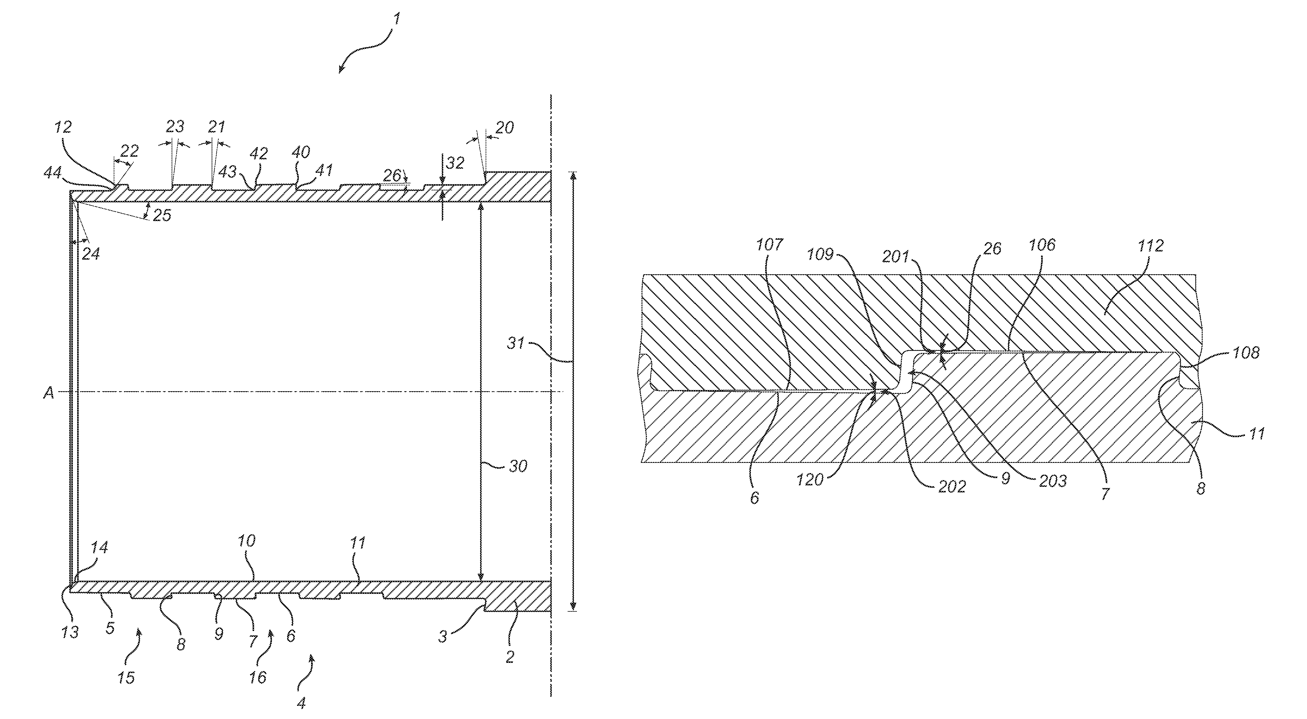
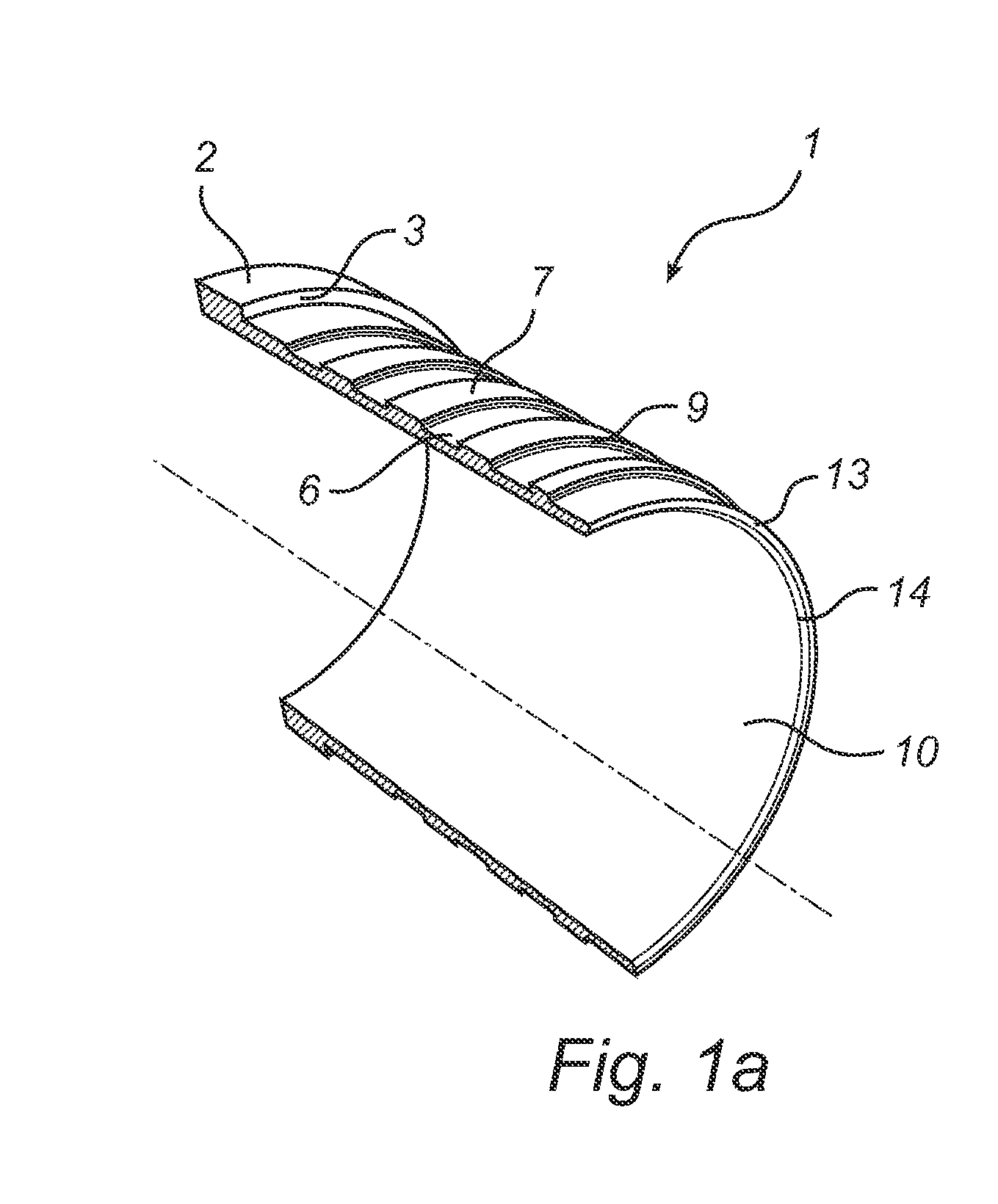
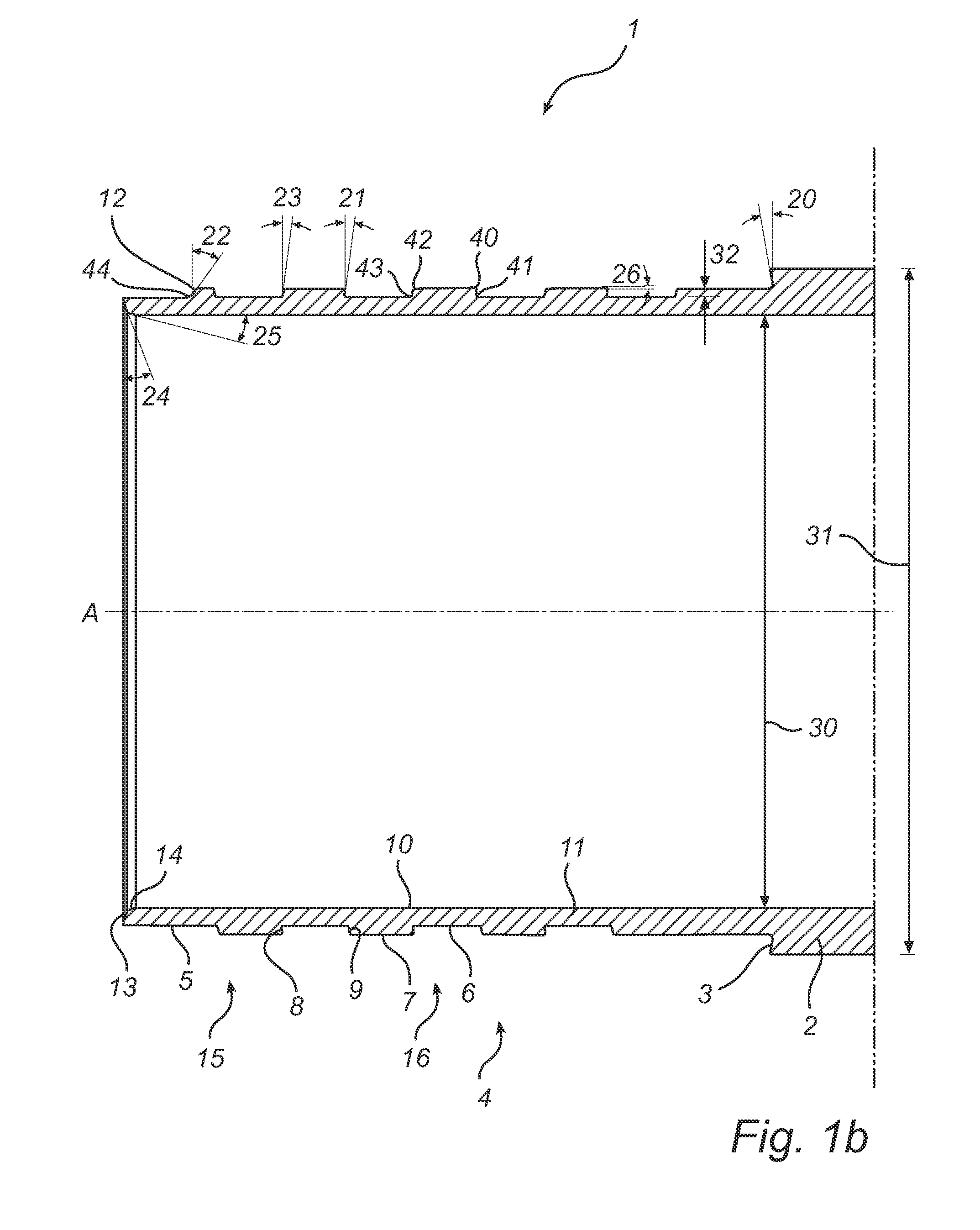
[0039]With reference to FIGS. 1a and 1b, a male member 1 of a joint for a drill tube is shown. The inner diameter 30 of the tubular tube and joint, as well as the outer diameter 31, may be specified for an industrial standard. A base portion 2 of the cylindrical member has the same outer diameter 31 as the drill tube, and a base shoulder 3 connects the base portion 2 with the outer portion of the member that is provided with a thread 4. The thread extends along the axial length of the member 1, and ends at an end portion 5.

[0040]The thread 4 presents a thread bottom 6, a thread top 7, a pressure flank 8 and a clearance flank 9. The thread bottom 6 is defined as the part of the thread with the shortest radial distance from the central axis A. The part with longer radial distance from the central axis is the thread top 7. The greatest radial distance between the thread bottom 6 and the thread top 7 defines the thread depth 32. An inner cylindrical surface 10 of the member 1 defines, t...


PUM


Abstract

A member of a joint for a thin-walled drill tube presents a central axis and has a thread for forming a screw joint. The thread presents a thread bottom, a thread top, a pressure flank and a clearance flank. The pressure flank presents a portion having a negative angle less than 7.5°, but at least 0°, relative to a direction perpendicular to the central axis.

Description

CROSS REFERENCE TO RELATED APPLICATIONS[0001]This application is a §371 National Stage Application of PCT International Application No. PCT / SE2010 / 050173, filed Feb. 16, 2010, and claims priority under 35 U.S.C. §119 and / or §365 to Swedish Application No. 0900388-0, filed Mar. 26, 2009, the disclosures of both of which are incorporated herein in their entirety by reference.FIELD OF THE INVENTION[0002]This disclosure relates to joints for drill tubes, and in particular threaded joints for thin-walled drill tubes.BACKGROUND[0003]A joint for a drill tube transfers the torque power from one tube part to another. Because of a thinner wall thickness, the joint is generally weaker than the rest of the tube. At a certain drilling depth, the tube gets so long that the weight becomes greater than the desired drilling thrust. To keep the desired drilling thrust at the drill bit end of the tube, an increased pullback tension load is required at the opposite end of the drill tube. Therefore, whe...

Claims


Application Information

Patent Timeline
Patent Type & Authority Patents(United States)
IPC IPC(8): F16L15/00E21B17/042F16L25/00
CPCE21B17/0426F16L15/006E21B17/042E21B17/0423
Inventor BACK, GORAN
Owner SANDVIK INTELLECTUAL PROPERTY AB
Learn More