Laser cutting machine

a laser cutting machine and laser technology, applied in metal-working equipment, welding equipment, manufacturing tools, etc., can solve the problems of limiting the production rate, inertia of the laser even in this machine, and suboptimal cutting, so as to increase the productivity of the laser cutting machine

Active Publication Date: 2014-12-30
MITSUBISHI ELECTRIC RES LAB INC
View PDF11 Cites 20 Cited by
  • Summary
  • Abstract
  • Description
  • Claims
  • Application Information

AI Technical Summary

Benefits of technology

[0012]It is an object of the invention to increase productivity of a laser cutting machine.
[0013]It is further object of the invention to increase productivity of the laser cutting machine suitable for cutting large parts of a workpiece with fine details.
[0014]It is further object of the invention to minimize moving mass of a low-inertia beam directing mechanism of a large-workpiece laser cutter machine.
[0015]It is further object of the invention to avoid mechanical crashes of the components of the laser cutting machine and to simplify the controlling of the machine.
[0016]Some embodiments of the invention are based on a realization that the speed of a laser cutter machine can be improved by using a fast, low-inertia galvano arranged on a platform configured to move in a plane parallel to a workpiece over a length substantially equal to a length of the workpiece. The motion of the platform overcomes the limitations on a small working area of the galvano, and the galvano overcomes limitation of the inertia of the platform. Moreover, the rigidity of the platform and the motion of the platform suitable for precise cutting can be facilitated by prismatic joints.
[0017]Furthermore, the galvano can be arranged on the platform such that mechanical crashes of the galvano and the platform are precluded. Such arrangement allows for simplification of the controlling operation of the laser cutting machine. Moreover, such arrangement allows for summing the motions of the galvano and the platform to increase the speed of the laser cutting. Also, arranging the galvano on the platform in the position fixed with respect to the workpiece further allows increasing the speed of the laser cutting. For example, by orienting the galvano at 45 degrees from the motion of the platform, so the common horizontal and vertical cuts can be done simultaneously by both the motion of both galvano axes and the relevant axis motion of the platform. Such orientation result in gaining another factor of 1.4 in cutting speed.

Problems solved by technology

A limiting factor on production rate is directly related to the inertia of the components of the laser cutting machine.
However, the inertia of the laser even in this machine is still relatively large, as the laser focusing lens itself is moved.
Such motion also stresses the precision optics of the laser focusing lens and may lead to a suboptimal cut.
However, avoidance of “robot arm crashes” in this design, i.e., situations where the robot arm tries to pass through itself or through the workpiece, is computationally difficult, and requires not only an accurate model of the robot arm and scanhead, but also a continuously evolving model of the workpiece during different stages of the cutting process, because a forbidden motion at one stage in the cutting process may be available for another stage of the process.

Method used


Image

  • Laser cutting machine
  • Laser cutting machine
  • Laser cutting machine

Examples


Embodiment Construction

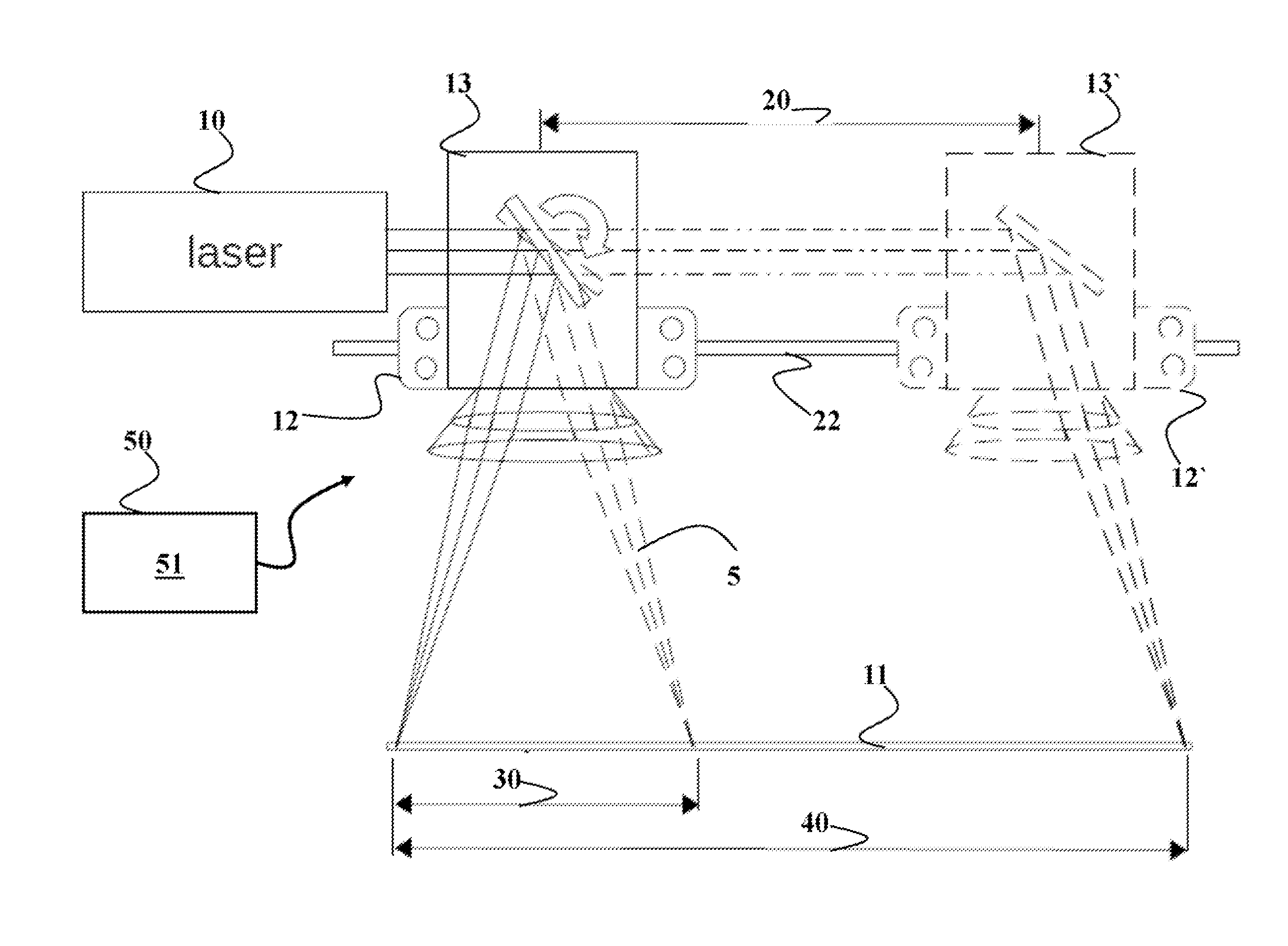
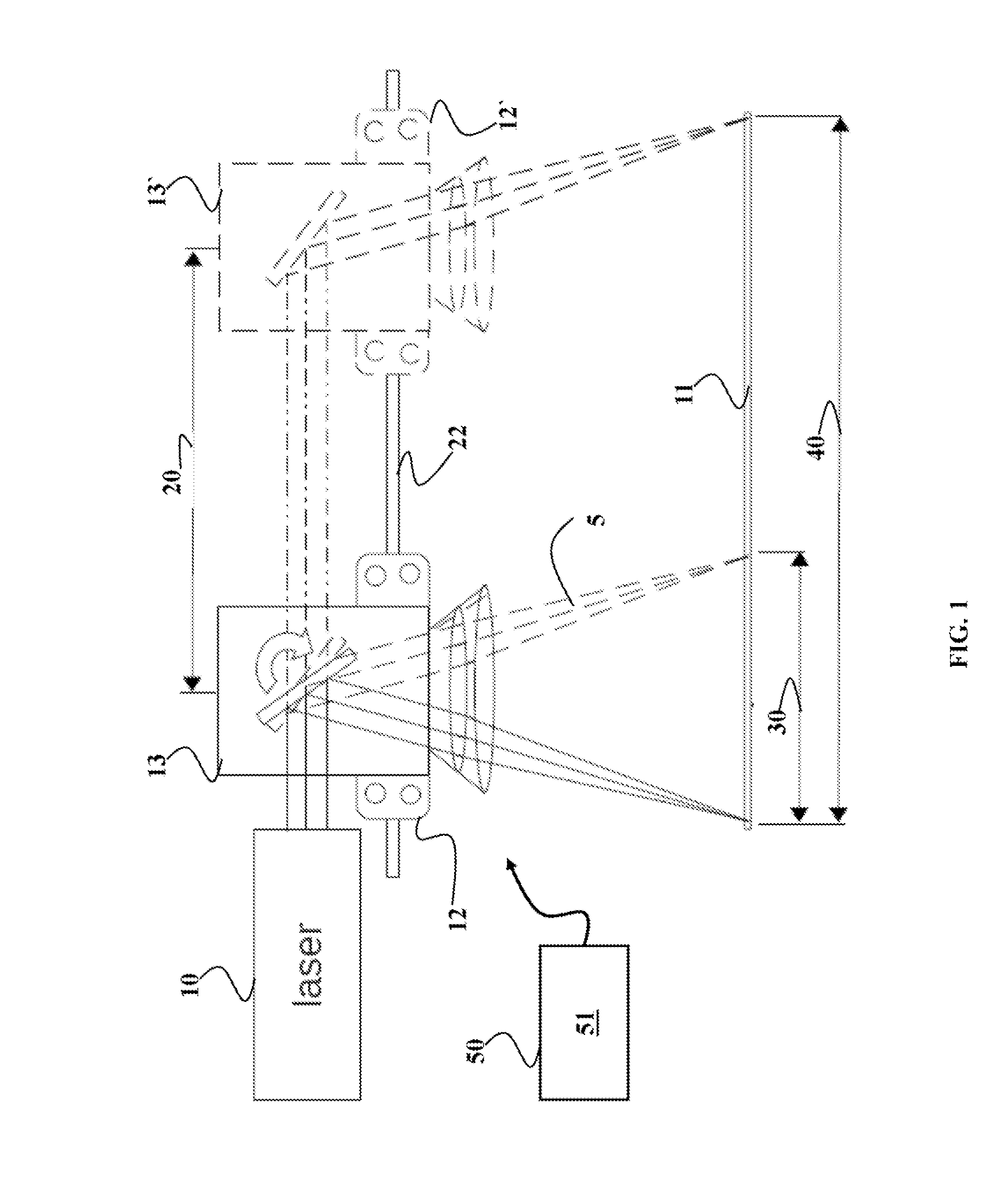
[0028]FIG. 1 shows a block diagram of a laser cutting machine suitable for controlling a position of a beam produced by a laser 10 on a workpiece 11. The laser cutting machine includes a platform 12 configured to move along at least a first direction 20. The platform is moved by a motion system 22 for moving the platform in a plane parallel to the workpiece. In one embodiment, the motion system 22 includes a first prismatic joint facilitating a first motion of the platform along the first direction 20.

[0029]The laser cutting machine also includes a galvano 13 arranged on the platform 12, such that the motion of the platform along the first direction 20 causes a motion of the galvano along the first direction. For example, the galvano can include a reversible DC motor, equipped with a mirror on an output shaft, and usually with built-in bump stops, to limit rotation of the mirror to a small angle, typically + / −20 to 30 degrees about the center. Such galvanos are often sold as complet...


PUM

PropertyMeasurementUnit
angleaaaaaaaaaa
diameteraaaaaaaaaa
angleaaaaaaaaaa

Abstract

A laser cutting machine includes a platform and a motion system. The motion system includes a first prismatic joint facilitating a first motion of the platform along a first direction and a second prismatic joint facilitating a second motion of the platform along a second direction. A galvano arranged on the platform, such that a motion of the platform causes a motion of the galvano, the galvano including a first mirror, wherein a third motion of the first mirror positions the laser beam along a third direction, and a second mirror, wherein a fourth motion of the second mirror positions the laser beam along a fourth direction. A control module controls concurrently the motion system and the galvano, such that a position of the laser beam on the workpiece is a vector sum of the first motion, the second motion, the third motion, and the fourth motion.

Description

FIELD OF THE INVENTION[0001]This invention relates generally to a laser cutting machine, and more particularly to a system for directing a laser beam of a laser cutting machine at a workpiece.BACKGROUND OF THE INVENTION[0002]Common methods of operation in laser cutting machines for sheet materials perform two-dimensional (2D) relative motion between a laser and a workpiece, such that a laser beam cuts the workpiece as the beam moves. In such machines, there are three options. A position of the laser is fixed and the workpiece is moved in X and Y directions. A position of the workpiece is fixed and the laser is moved in the X and the Y directions. The laser is fixed in the Y direction and moves in the X direction, and the workpiece is fixed in X direction and moves in Y direction.[0003]For example, a laser tube cutter fixes the position of the laser, and the position of the workpiece is translated and rotated to a focus point of the laser. In contrast, large CO2 laser cutters used fo...

Claims


Application Information

Patent Timeline
Patent Type & Authority Patents(United States)
IPC IPC(8): B23K26/38B23K26/08
CPCB23K26/0876B23K26/08B23K26/38B23K26/0807B23K26/082
Inventor YERAZUNIS, WILLIAM S.BARNWELL, III, JOHN C.BORTOFF, SCOTT A.SHILPIEKANDULA, VIJAYGOLDSMITH, ABRAHAM
Owner MITSUBISHI ELECTRIC RES LAB INC
Why Eureka
Try Eureka