
Dichroic dye composition, light absorption anisotropic film, and polarizing element

a technology of anisotropic film and dye composition, which is applied in the direction of polarizing elements, nuclear engineering, synthetic resin layered products, etc., can solve the problems of insufficient heat resistance and light fastness of the dye composition, and the inability to obtain the ideal achromatic color polarizing element in the entire visible spectral region, and achieve excellent heat resistance and light fastness, and excellent polarization performance

Active Publication Date: 2015-01-06
FUJIFILM CORP
View PDF21 Cites 8 Cited by
  • Summary
  • Abstract
  • Description
  • Claims
  • Application Information

AI Technical Summary

Benefits of technology

The present invention provides a new type of light absorption film that is almost color-blind, meaning it doesn't show much different colors. This film can be used to make an achromatic polarizing element, which is very durable and can withstand heat and light. It is also very good at making things look good and being strong.

Problems solved by technology

However, in the case where iodine is used for the polarizing element, heat resistance and light fastness thereof are not sufficient since iodine has a large sublimation property.
Further, the extinction color becomes deep blue, and an ideal achromatic color polarizing element in the entire visible spectral region cannot necessarily be obtained.
However, in employing the organic dyes, there is a problem, for example, that only polarizing elements are obtained, which is distinctly inferior in dichroic property to those employing iodine.
However, in this method, there is a problem, for example, that time and effort are required for steps such as a stretching treatment.
However, it has been known that there has been a problem in the heat resistance in the method described in the literature.
Accordingly, there are many cases that even the conventional dyes, that may be used in the polarizing elements underwent the above-mentioned stretching treatment, are not suitable for the wet film-forming method.
However, although such materials are suitable for the process, they have had a problem that they have not been able to show high dichroism.
However, in the case where an anisotropic dye film is obtained by combining the several kinds of dichroic dyes, there is a problem that since different molecules are mixed, the orientation of the molecules is disturbed and obtaining a high dichroism is difficult.
However, the compound has a problem that the dichroism and the absorbance at a long-wavelength region are insufficient.

Method used


Image

  • Dichroic dye composition, light absorption anisotropic film, and polarizing element
  • Dichroic dye composition, light absorption anisotropic film, and polarizing element
  • Dichroic dye composition, light absorption anisotropic film, and polarizing element

Examples


example 1

[0366]2 parts by mass of the exemplified dye (A-46) was dissolved in 98 parts by mass of chloroform with stirring, to obtain a dye solution for a light absorption anisotropic film (coating liquid). The dye solution was coated by spin coating on a glass substrate having a polyvinyl alcohol alignment film (trade name: PVA-103, manufactured by Nissan Chemical Industries, Ltd.) that had been subjected to a homogeneous alignment treatment by rubbing, followed by spontaneously drying and heating at 70° C. for 1 minute, to obtain a light absorption anisotropic film.

[0367]The thickness of the film was 0.2 μm.

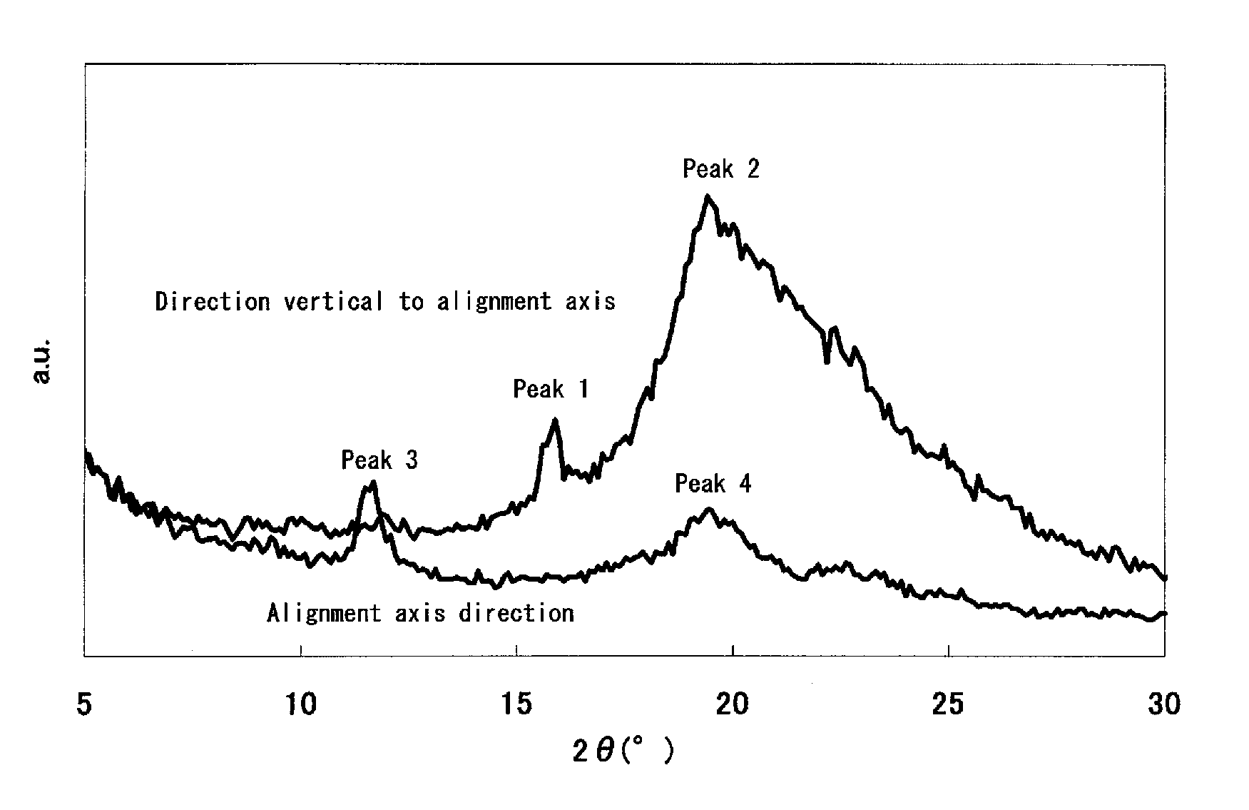
[0368]The thus-obtained light absorption anisotropic film had a dichromatic ratio of 21. The X-ray diffraction pattern obtained from the direction vertical to the alignment axis (the direction in which the diffraction surface vertical to the transmission axis is observed) and the alignment axis direction (the direction in which the diffraction plane vertical to the absorption axis is ob...

example 2

[0370]2 parts by mass of the exemplified dye (A-58) was dissolved in 98 parts by mass of chloroform with stirring, to obtain a dye solution for a light absorption anisotropic film. The dye solution (coating liquid) was coated by spin coating on a glass substrate having a polyvinyl alcohol alignment film (trade name: PVA-103, manufactured by Nissan Chemical Industries, Ltd.) that had been subjected to a homogeneous alignment treatment by rubbing, followed by spontaneously drying and heating at 40° C. for 1 hour, to obtain a light absorption anisotropic film. The thickness of the film was 0.2 μm.

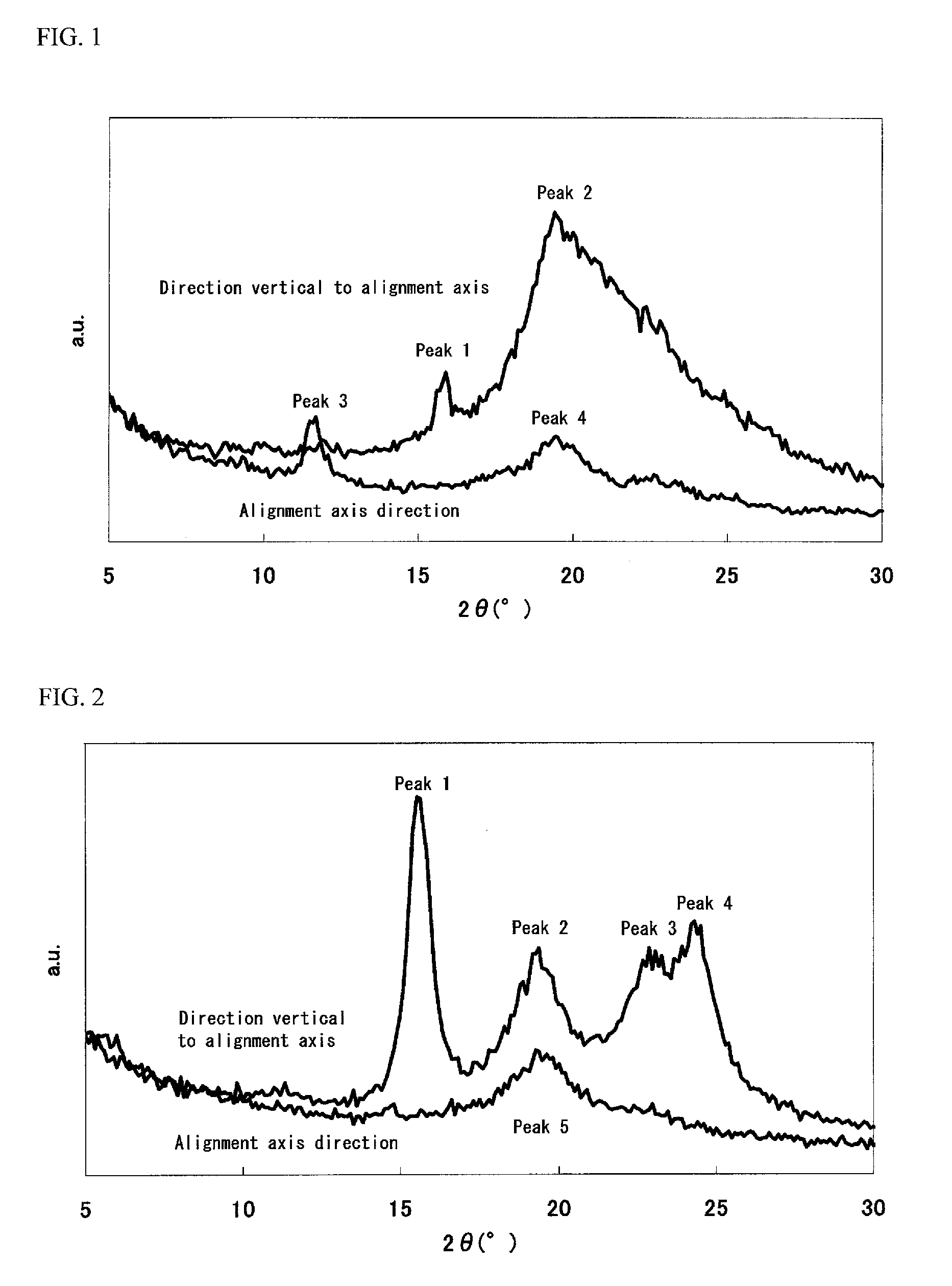
[0371]The thus-obtained light absorption anisotropic film had a dichromatic ratio of 18. The X-ray diffraction pattern obtained from the direction vertical to the alignment axis and the alignment axis direction of the film is shown in FIG. 2. Four peaks were detected in the direction vertical to the alignment axis, and one peak was detected in the alignment axis direction. The periods and half...

example 3

[0373]2 parts by mass of the exemplified dye (C-10) was dissolved in 98 parts by mass of chloroform with stirring, to obtain a dye solution for a light absorption anisotropic film. The dye solution (coating liquid) was coated by spin coating on a glass substrate having a polyvinyl alcohol alignment film (trade name: PVA-103, manufactured by Nissan Chemical Industries, Ltd.) that had been subjected to a homogeneous alignment treatment by rubbing, followed by spontaneously drying and heating at 40° C. for 1 hour, to obtain a light absorption anisotropic film. The thickness of the film was 0.2 μm.

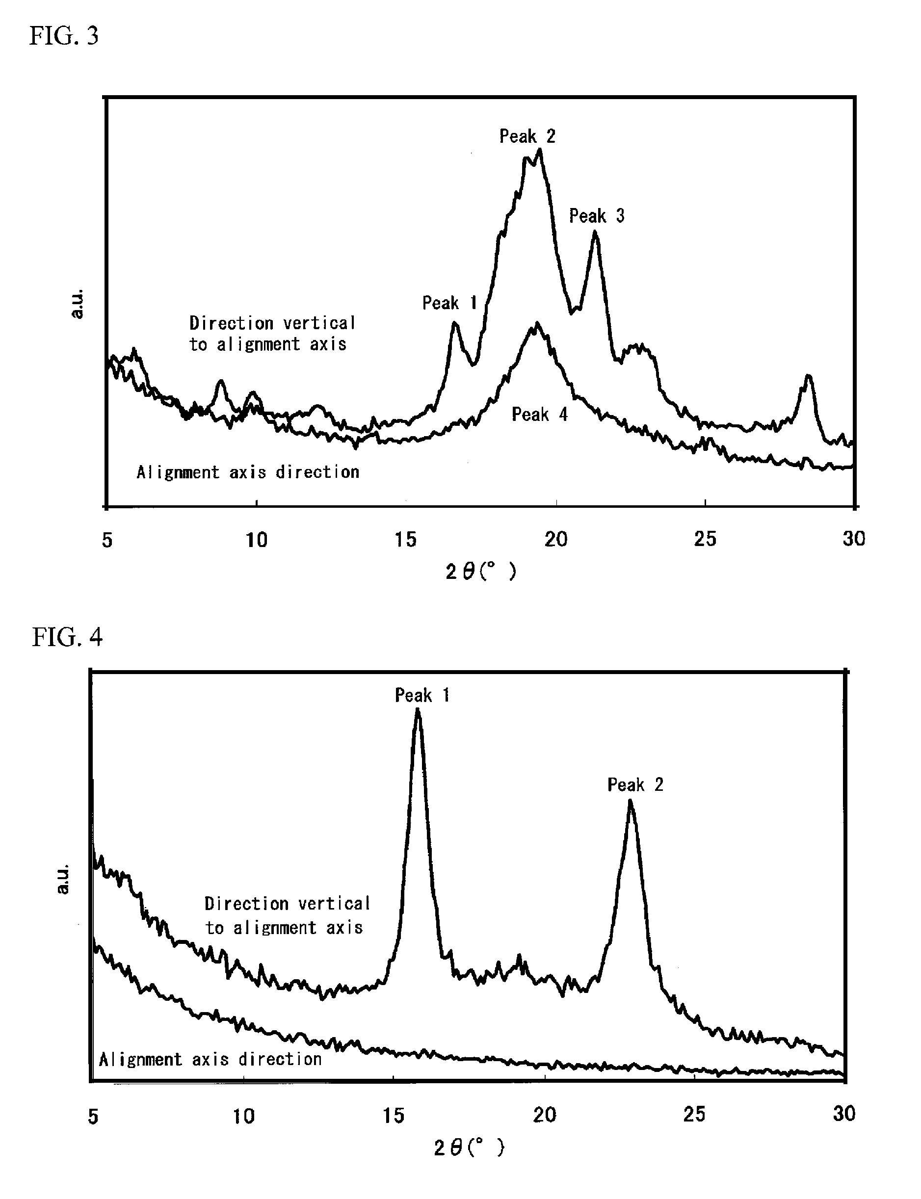
[0374]The thus-obtained light absorption anisotropic film had a dichromatic ratio of 18. The X-ray diffraction pattern obtained from the direction vertical to the alignment axis and the alignment axis direction of the film is shown in FIG. 3. Two peaks were detected in the direction vertical to the alignment axis. The periods and half widths obtained from the respective peaks are shown in Tabl...


PUM

PropertyMeasurementUnit
thicknessaaaaaaaaaa
mass %aaaaaaaaaa
mass %aaaaaaaaaa

Abstract

A light absorption anisotropic film, having at least one dichroic dye, in which the light absorption anisotropic film shows a diffraction peak derived from a periodic structure in a direction in a plane of the light absorption anisotropic film in X-ray diffraction measurement and the diffraction peak has a half width of 1.0 Å or less.

Description

TECHNICAL FIELD[0001]The present invention relates to a dichroic dye composition containing at least one kind of dichroic dye for forming a novel light absorption anisotropic film. Further, the present invention relates to a light absorption anisotropic film, which employs the composition and has a periodic structure in the direction vertical to an alignment axis in a plane of the film. Further, the present invention relates to a polarizing element and a display device, each employing the light absorption anisotropic film.BACKGROUND ART[0002]When an attenuating function, a polarizing function, a scattering function, a light-shielding function, or the like is required for an irradiated light such as laser light and natural light, apparatuses have conventionally been adapted, which operate based on principles different from each other, depending on the functions. Thus, the products corresponding to the functions have been prepared by the production processes different from each other,...

Claims


Application Information

Patent Timeline
Patent Type & Authority Patents(United States)
IPC IPC(8): C09B31/30B05D5/06C09B31/28B05D3/06C09B31/04C09B31/08C09B31/18C09B56/02C09B56/08G02B5/22G02B5/30
CPCG02B5/3033C09B31/04C09B31/08C09B31/18C09B31/28C09B31/30C09B56/02C09B56/08G02B5/223G02B5/3016G02F2202/40C09K2323/031G02B5/30G02F1/1335
Inventor IWAHASHI, NOBUTAKAOGIYAMA, MASASHIMORISHIMA, SHINICHI
Owner FUJIFILM CORP
Learn More