Method and apparatus for controlling ventilation systems

a technology of ventilation system and control method, which is applied in the direction of energy-efficient heating/cooling, space heating and ventilation details, and domestic heating details, etc. it can solve the problems of reducing energy efficiency, limited speed, and excessive noise and vibration due to harmonics, so as to increase the speed of the supply fan and reduce the speed of the exhaust fan. , the effect of increasing the thermal efficiency of the supply airflow

Active Publication Date: 2015-01-27
AIR TECH EQUIP
View PDF16 Cites 18 Cited by
  • Summary
  • Abstract
  • Description
  • Claims
  • Application Information

AI Technical Summary

Benefits of technology

[0034]Preferably, the supply fan speed is increased or the exhaust fan speed is decreased where the thermal efficiency for the supply airflow is greater than the thermal efficiency for the exhaust fan.
[0035]Preferably, the supply fan speed is decreased or the exhaust fan speed is increased where the thermal efficiency for the supply airflow is less than the thermal efficiency for the exhaust fan.

Problems solved by technology

These existing solutions present several inconveniences including a limited number of speeds, excessive noise and vibration due to harmonics and reduced energy efficiency.
In addition, these techniques also allow for a low number of fan speeds, typically three, which can result in lower ventilation efficiency.
Furthermore, installed ventilation systems often exhibit lower ventilation efficiency than was measured during product testing, resulting in a suboptimal amount of sensible and latent energy being transferred between the exhaust and supply airflows.
This is due in part to unbalanced supply and exhaust airflows.
A number of factors can lead to this unbalance, including the length and type of the air ducts leading to and from the ventilator and dirty air filters blocking the flow of air.
Current ventilation systems do not provide a means for detecting and automatically correcting unbalanced airflows.
Another issue affecting the performance of ventilation systems is the lack of real-time data concerning indoor and outdoor atmospheric conditions to be used in control algorithms.
Current systems do not incorporate the means (for example, but not limited to, sensors) necessary for the automated, optimized control of a ventilation system, based on outdoor and indoor environmental conditions.

Method used


Image

  • Method and apparatus for controlling ventilation systems
  • Method and apparatus for controlling ventilation systems
  • Method and apparatus for controlling ventilation systems

Examples


Embodiment Construction

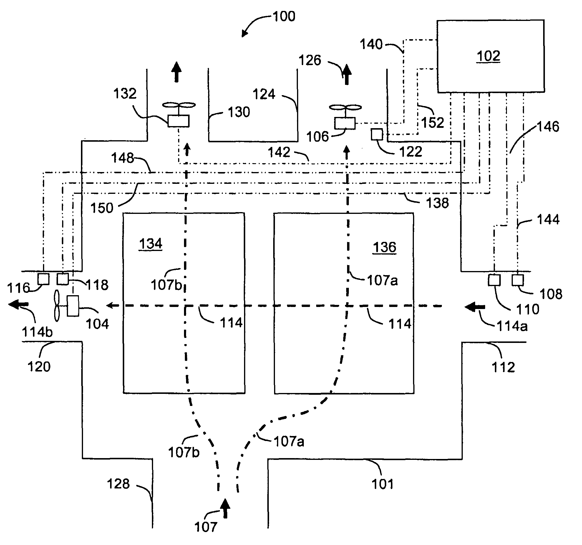
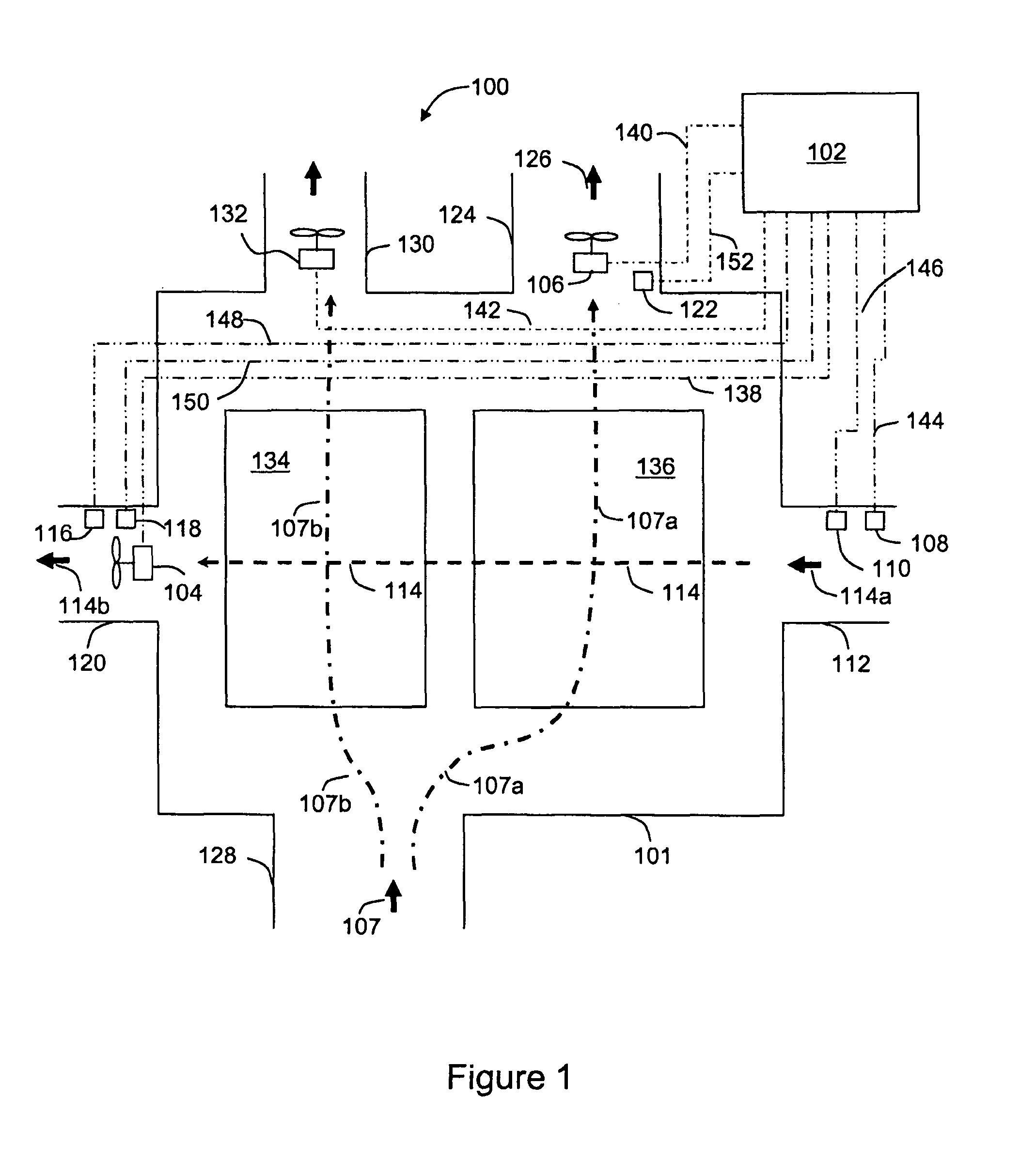
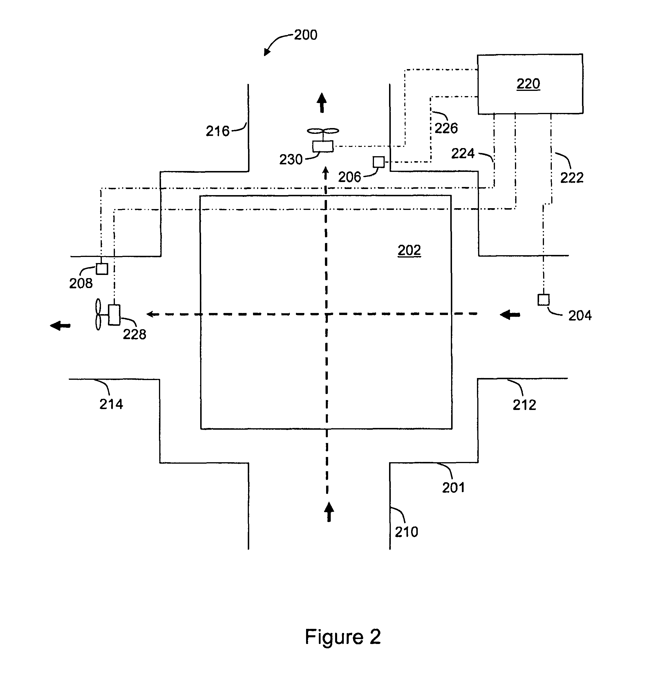
[0045]In accordance with one embodiment of the present invention, a first temperature sensor may be positioned in the supply airflow at a position proximate to a supply inlet of the ventilator. A second temperature sensor may be positioned in the supply airflow at a position proximate to a supply outlet of the ventilator. A third temperature sensor may be positioned in the exhaust airflow at a position proximate to the exhaust outlet of the ventilator. Optionally, a fourth temperature sensor may be positioned in the return airflow at a position proximate to the exhaust inlet of the ventilator.

[0046]An energy exchange core, such as a heat exchange core or an enthalpy exchange core, may also be provided where the supply airflow and the exhaust airflow do not mix in the ventilator. Alternatively, the airflows may mix in the ventilator in the absence of a core. Energy transfer may occur between the supply and exhaust airflows, with heat and / or moisture transferred therebetween.

[0047]A r...


PUM


Abstract

An energy recovery ventilation system is described which allows for continuous fan speed control through pulse width modulation of direct current fans. The energy recovery ventilation described is capable of fine motor speed control without the disadvantages of high noise, low efficiency and a fixed number of speeds present in commonly-used speed-varying techniques used with alternating current (AC) fans. This may be accomplished through the use of direct current (DC) fans and pulse width modulation. A controller is used to optimize the ventilation and energy efficiency of the system through the use of several temperature sensors. The energy recovery ventilation also provides a control process for self-optimization of the energy recovery ventilation, in case the supply and exhaust airflows are unequal. An unbalance may be detected by calculating the thermal efficiencies of the exhaust and supply airflows.

Description

RELATED APPLICATION[0001]This application claims the benefit of Canadian Patent Application No. 2,596,151, filed Aug. 3, 2007.FIELD OF THE INVENTION[0002]The present invention generally relates to ventilation systems such as energy recovery ventilators and to methods and apparatus for controlling such ventilation systems.BACKGROUND OF THE INVENTION[0003]Current energy recovery ventilators rely on alternating current (AC) fans. Speed control of AC motors is generally accomplished using tapped transformers, triacs, capacitors or induction coils. These existing solutions present several inconveniences including a limited number of speeds, excessive noise and vibration due to harmonics and reduced energy efficiency. In addition, these techniques also allow for a low number of fan speeds, typically three, which can result in lower ventilation efficiency.[0004]Furthermore, installed ventilation systems often exhibit lower ventilation efficiency than was measured during product testing, re...

Claims


Application Information

Patent Timeline
Patent Type & Authority Patents(United States)
IPC IPC(8): F24F7/08F24F7/007F24F3/147F24F11/00F24F11/76F24F12/00
CPCF24F12/006F24F11/0079Y02B30/16Y02B30/746Y02B30/563F24F11/77Y02B30/56Y02B30/70Y02B30/00
Inventor BOUDREAU, PATRICK PAULBOULAY, MICHAEL
Owner AIR TECH EQUIP
Why Eureka
Try Eureka