Energy storage device

a technology of energy storage and energy storage, which is applied in the manufacture of fixed capacitors, fixed capacitor details, fixed capacitors, etc., can solve the problems of high cost due to expensive raw materials, many of the same reliability and scientific challenges, etc., and achieves the effect of increasing the electric field present, increasing the working voltage, and increasing the voltag

Active Publication Date: 2015-01-27
CARVER SCI INC
View PDF1 Cites 31 Cited by
  • Summary
  • Abstract
  • Description
  • Claims
  • Application Information

AI Technical Summary

Benefits of technology

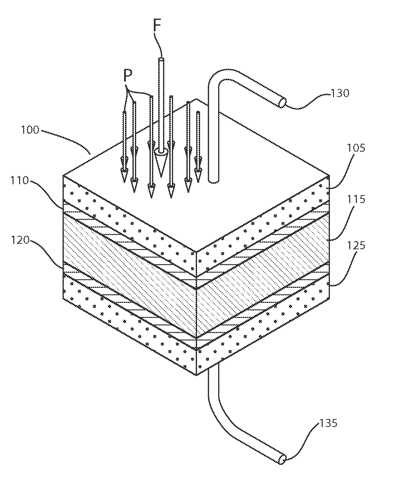
[0016]The nonconductive coatings constitute insulating layers that allow for much higher voltages to be employed than in traditional EDLCs. This extends the layers from just a few (two or three which alternate in charge) to many (possibly orders of magnitude more in number) which can reach far into the dielectric medium. The increase in working voltage, significantly increases the electric field present in the capacitor and energy stored in the capacitor.
[0017]In one embodiment, the dielectric material is a variable viscosity dielectric material. In other words, the viscosity may be increased or decreased in a controlled manner, such as in response to an applied external stimulus. By way of example, the external stimulus may be a force, a pressure, a shear stress, a normal stress, heat, a heat sink, a coolant, a magnetic field, or an electric field. The external stimulus may comprise a mechanism from the group consisting of a controllable heat source, a heat sink, a coolant, a controllable cooling source, a controllable magnetic field generator, a controllable electric field generator, a controllable force generator, a controllable pressure generator, or a controllable shear stress generator. Viscosity of the dielectric can be made to gradually increase from electrode layer to electrode layer sequentially, or vice versa. With a viscosity increase, the discharge of the Helmholtz and Diffuse Helmholtz layers as thermal energy can be slowed and essentially halted with complete solidification. Electrical energy can thereby be stored for extended periods of time until ready for release. When ready for release, the viscosity may be reduced in a controlled manner such as by removing a viscosity-increasing stimulus or by applying a viscosity-decreasing stimulus. The reduction of viscosity facilitates discharge.

Problems solved by technology

They thus can store much more energy than conventional planar surface capacitors, but face many of the same reliability and scientific challenges as advanced batteries, including high cost due to expensive raw materials and complex processing.

Method used


Image

  • Energy storage device
  • Energy storage device
  • Energy storage device

Examples


Embodiment Construction

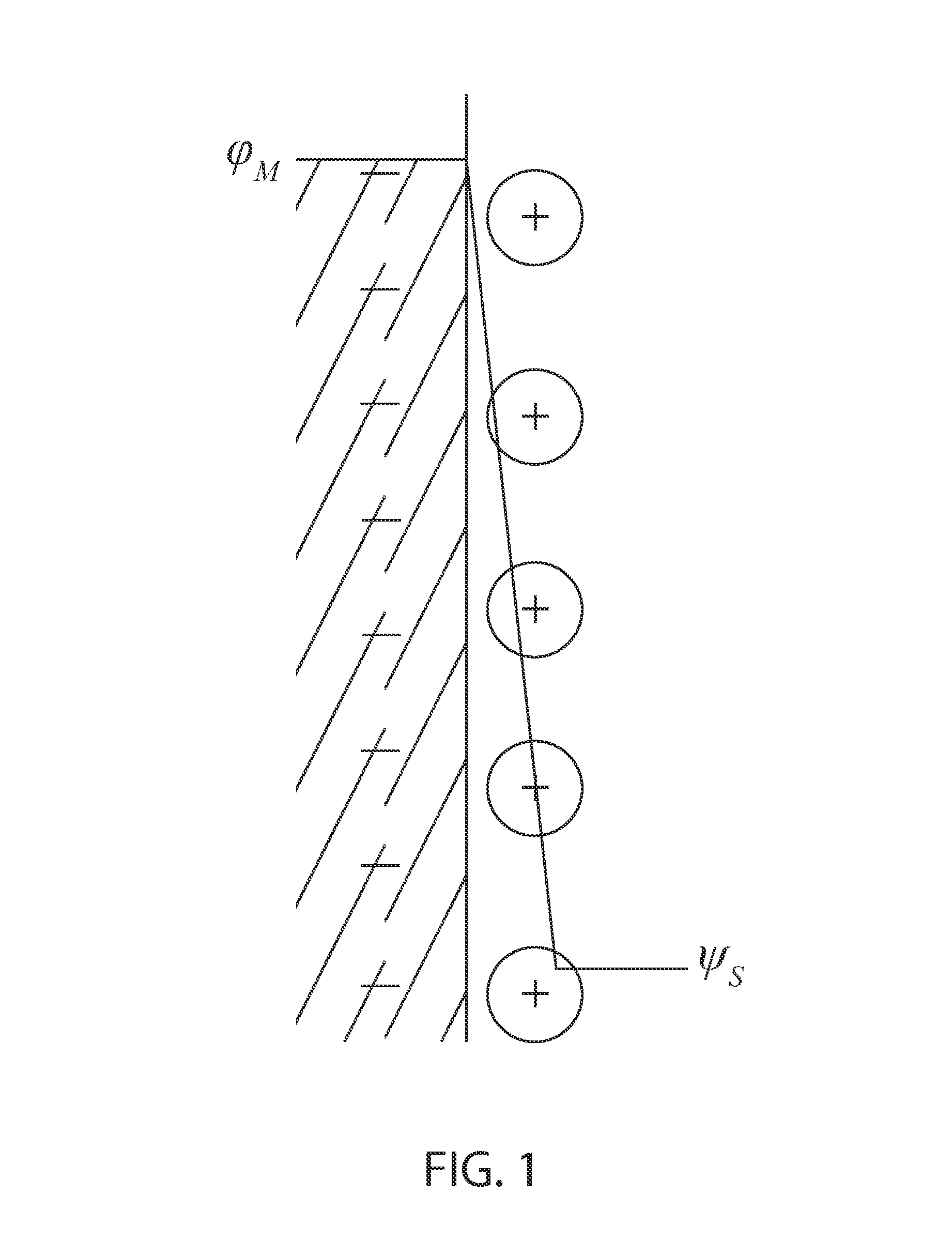
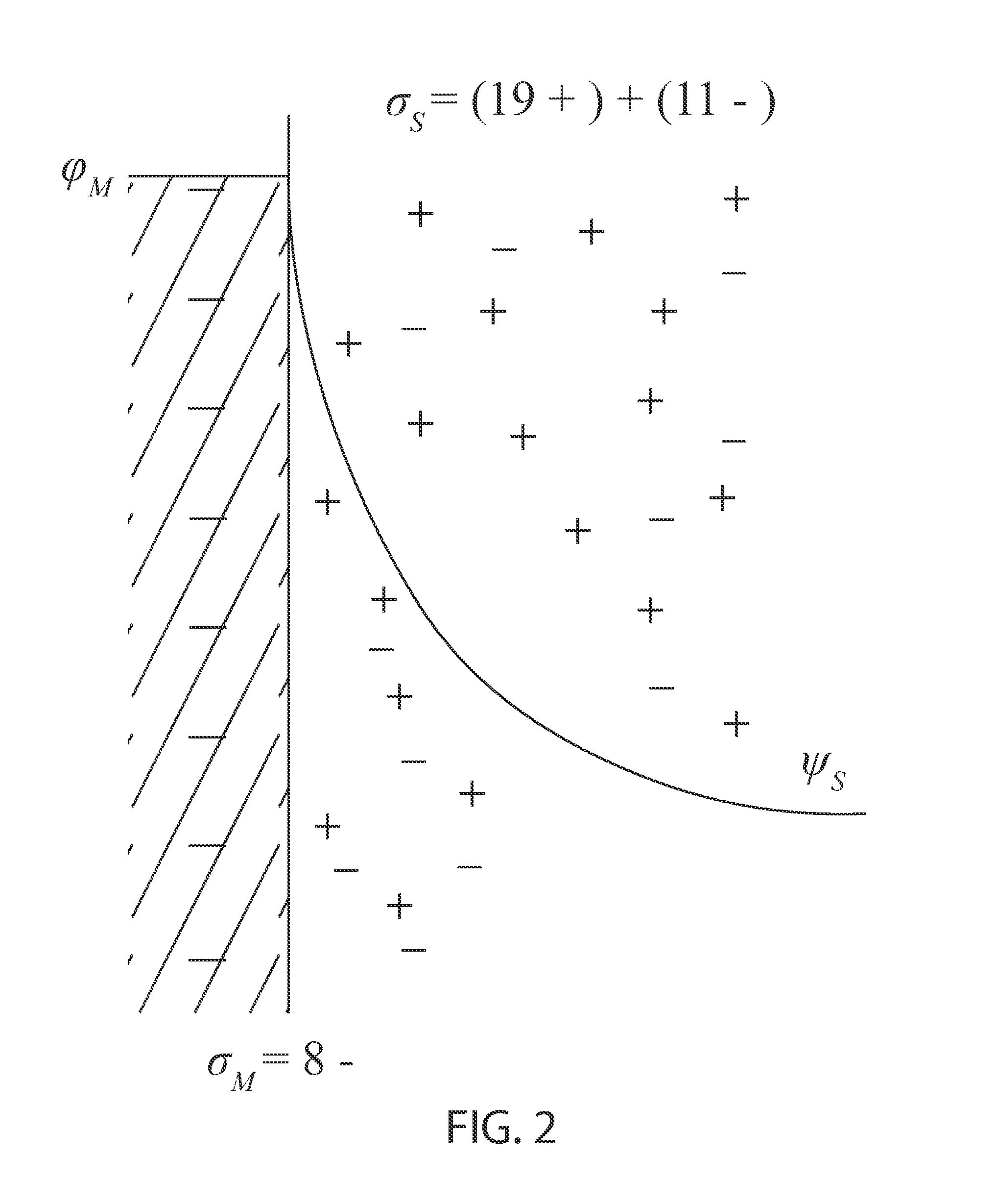
[0035]In an exemplary embodiment of an energy storage device according to principles of the invention, an insulating layer directly allows for much higher voltages to be employed than in traditional EDLCs. This in turn increases the number of layers from just a few (two or three which alternate in charge) to many (possibly orders of magnitude more in number) which can reach far into the dielectric medium. A treatment as series capacitors (a common way to analyze multilayer capacitance) demonstrates that, for a set amount of charge, adding more layers will actually decrease capacitance and increase voltage. This increase in working voltage (both directly and indirectly from the use of an insulating layer) along with the small degree of charge separation previously observed in EDLCs, significantly increases the electric field present in the capacitor as can be seen from Eq. 1 (above). Worth further notice is the resulting dramatic increase in energy stored in the capacitor from the vo...


PUM

PropertyMeasurementUnit
thicknessaaaaaaaaaa
thicknessaaaaaaaaaa
thicknessaaaaaaaaaa

Abstract

An energy storage device comprises a capacitor having a dielectric between opposite electrodes and a nonconductive coating between at least one electrode and the dielectric. The nonconductive coating allows for much higher voltages to be employed than in traditional EDLCs, which significantly increases energy stored in the capacitor. Viscosity of the dielectric material may be increased or decreased in a controlled manner, such as in response to an applied external stimulus, to control discharge and storage for extended periods of time.

Description

RELATED APPLICATION[0001]This application is a nonprovisional of and claims the benefit of priority of U.S. Provisional Application 61 / 808,733 filed 5 Apr. 2013, and a continuation in part of U.S. Nonprovisional application Ser. No. 13 / 853,712 filed 29 Mar. 2013, and a continuation in part of U.S. Nonprovisional application Ser. No. 13 / 599,996 filed 30 Aug. 2012, the entire contents of which are incorporated herein by this reference and made a part hereof.FIELD OF THE INVENTION[0002]This invention relates generally to an energy storage device, and, more particularly, to an electro-active electrical component used to store energy electrostatically in an electric field.BACKGROUND[0003]There has been a recent trend in the use of electrochemical capacitors for enhanced storage of electrical energy. These capacitors derive their enhanced characteristics from two primary mechanisms: double layer capacitance and pseudocapacitance. Double layer-type capacitors use an electrical double layer...

Claims


Application Information

Patent Timeline
Patent Type & Authority Patents(United States)
IPC IPC(8): C08F210/00H01G9/00H01G4/018H01G4/04H01G4/20H01G11/78H01G13/00H02J7/34
CPCH01G11/78H01G13/00H01G4/018H01G4/04H01G4/206H02J7/345Y02T10/7022Y02T10/70H01G11/28H01G11/74
Inventor CARVER, DAVID R.CARVER, ROBERT G.REYNOLDS, SEAN W.HALL, SEAN CLAUDIUSDAVIS, NOAH ANTHONY
Owner CARVER SCI INC
Why Eureka
Try Eureka