Structure for gunpowder charge in multi-frac composite perforating devices

a multi-frac composite and perforating device technology, applied in the field of oil exploration and exploitation, can solve the problems of reducing the amount of gunpowder charged, the effect of being very poor, and the duration of the effective pressure of the multi-frac composite perforating device still needs further improvement, so as to reduce the assembly time, reduce the cost of transportation and storage, and simplify the assembly process

Active Publication Date: 2015-02-03
TONG OIL TOOLS CO LTD +1
View PDF100 Cites 3 Cited by
  • Summary
  • Abstract
  • Description
  • Claims
  • Application Information

AI Technical Summary

Benefits of technology

[0004]The problem to be solved by the present invention is to provide a structure for gunpowder charge in multi-frac combined perforating devices, which can increase the charge volume, prolong the duration of the effective pressure and thus enhance the fracturing effect.
[0013]The proppant may also be charged in the side-hung powder cases 2A and 2B outside the charge frame. In one embodiment, gunpowder box 2A is entirely charged with proppant, while gunpowder box 2B is entirely charged with gunpowder. In another embodiment, gunpowder box 2A is entirely charged with gunpowder, while gunpowder box 2B is only charged with proppant. In another embodiment, gunpowder box 2A are charged with both gunpowder and proppant, while gunpowder box 2B are charged with both gunpowder and proppant. In yet another embodiment, gunpowder box 2A is entirely charged with gunpowder, while both gunpowder and proppant are charged in gunpowder box 2B. During the perforation process, proppant from the side-hung gunpowder boxes can get into the formation along with the jet flow to support the crack formed and prevent the crack from closing, thus improving the seepage of the oil and gases.
[0015]In another embodiment, the triplet outer gunpowder box is attached onto the outer wall of the charge frame by a spring jig which implements the connection to the charge frame by a matching structure of a lock hook and a lock catch, e.g., a lock hook is provided on the outer side of one of the side-hung gunpowder boxes, and a lock catch matched to the lock hook is provided on the outer side of the other side-hung gunpowder box. This structure is simpler and facilitates on site assembly.
[0016]The charge volume can be increased by using the above charge arrangement to charge gunpowder with different burning rates into the gun and achieve the aim of prolonging the acting time of the pressure. The triplet outer gunpowder box is made of materials with high resistant to both cold and heat, thereby expanding the regions and types of formations for using this product.
[0017]In one embodiment, the perforating charge is ignited by the prima cord during perforation, the product from the explosion of the perforating charge first ignites gunpowder P in the middle gunpowder box 3 of the triplet outer gunpowder box, and then ignites gunpowder Q charged in the inner gunpowder box located between adjacent perforating charges inside the charge frame, and finally ignites gunpowders R1 and R2 charged in the side-hung gunpowder boxes 2A and 2B of the triplet outer gunpowder box outside the charge frame. In one embodiment, the time difference between the pressure peaks of the middle burning rate gunpowder and the high burning rate gunpowder is about 5-10 ms, and the time difference between the pressure peaks of the low burning rate gunpowder and the middle burning rate gunpowder is about 20-50 ms. Because of the time difference between the pressure peak among gunpowder of different burning rates, energy complementation is achieved, and the duration of the effective pressure in the tunnel is longer and up to 25-60 ms, thus fully enhanced the energy utilization and extended the length of the crack. The duration of the effective pressure 25˜60 ms is the sum of the 5˜10 ms time difference between the pressure peaks of the middle burning rate gunpowder and the high burning rate gunpowder and the 20˜50 ms time difference between the pressure peaks of the low burning rate gunpowder and the middle burning rate gunpowder.
[0019]As the present invention uses the triplet outer gunpowder box, there is no need to remove the positioning ring during assembly, and the three gunpowder boxes are assembled onto the charge frame simultaneously. Thus the assembly time is reduced and the assembly process is simplified. As compared to the cylindrical gunpowder boxes in the art, the triplet outer gunpowder box of the present invention occupies a smaller space and can be unfolded for easy package for transportation and storage. This drastically reduces the transport and storage cost of gunpowder. This type of structure is also easy for mass and standardized production.

Problems solved by technology

However, as the gunpowder is charged between the perforating charges in most integrated composite perforating gun, the amount of gunpowder charged is drastically decreased especially in cases where hole density is high, causing the effect to be very poor.
However, test results showed that the duration of the effective pressure of the multi-frac composite perforating device still need further improvement.

Method used


Image

  • Structure for gunpowder charge in multi-frac composite perforating devices
  • Structure for gunpowder charge in multi-frac composite perforating devices
  • Structure for gunpowder charge in multi-frac composite perforating devices

Examples


example 1

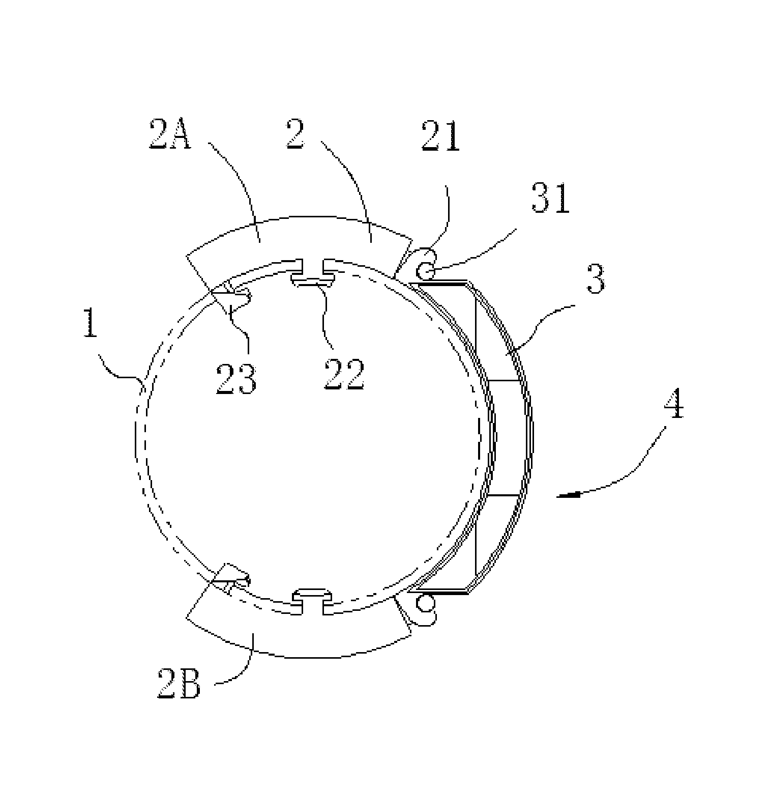
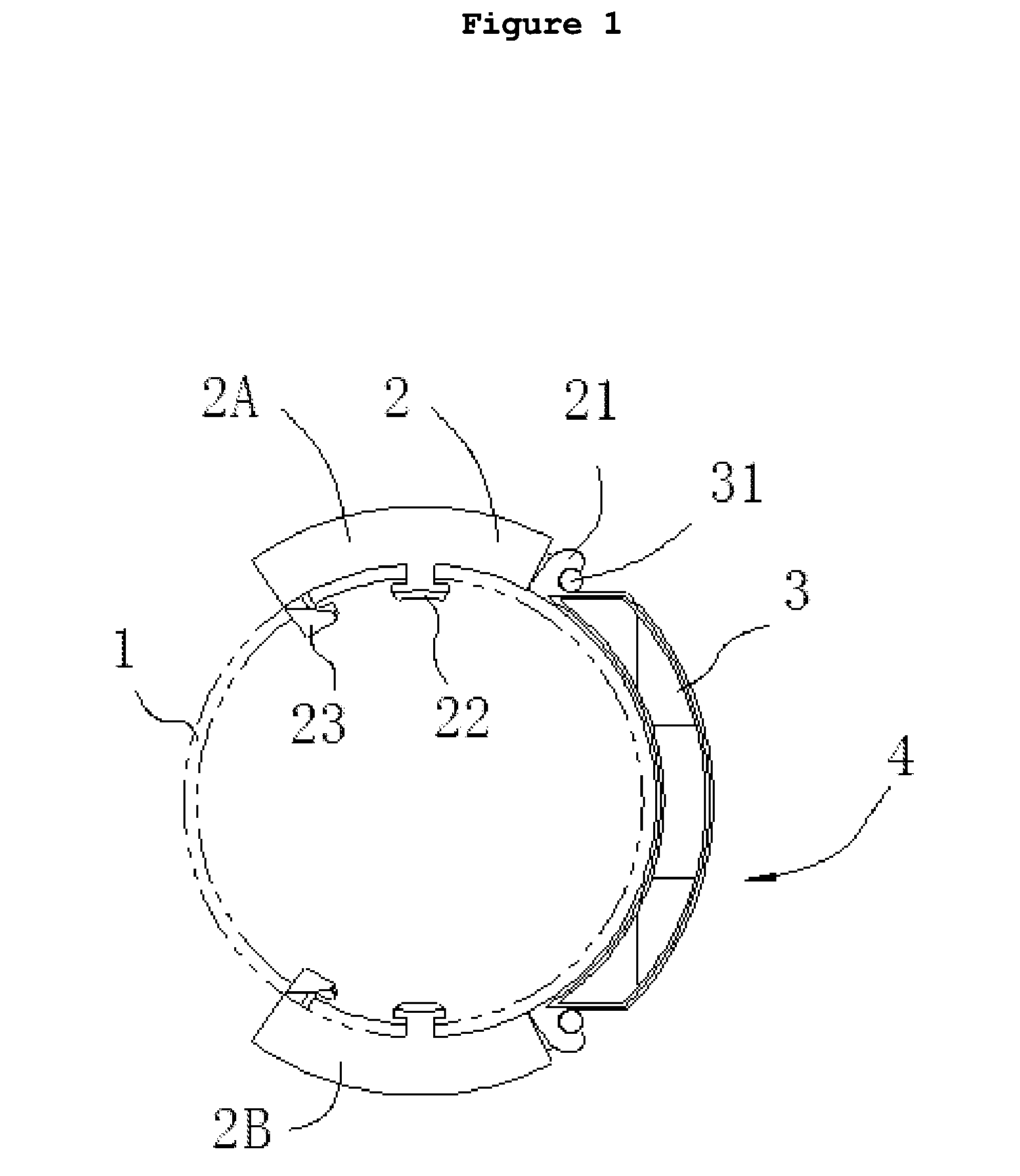
[0043]As shown in FIGS. 1 and 2, the multi-frac composite perforating device of this embodiment comprises three types of gunpowders with different burning rates, and the perforating device adopts a cylindrical charge frame. A triplet outer gunpowder box 4 is attached onto the outer wall of the cylindrical charge frame 1, and comprises a middle gunpowder box 3 and two side-hung gunpowder boxes 2A and 2B. The gunpowder P charged in the middle gunpowder box 3 outside the charge frame is high burning rate gunpowder, the gunpowder Q charged in the inner gunpowder box (not shown in the figure) between adjacent perforating charges inside the charge frame is low burning rate gunpowder and the gunpowders R1 and R2 charged in the side-hung gunpowder boxes 2A and 2B of the triplet outer gunpowder box are middle burning rate gunpowders with the same burning rate. There is no proppant charged in the side-hung gunpowder boxes 2A and 2B in this embodiment. The endpoint of combustion of the high bu...

example 2

[0049]As shown in FIGS. 7 and 8, the side-hung gunpowder boxes 2A and 2B in the triplet outer gunpowder box 4 in this embodiment are attached onto the outer wall of the cylindrical charge frame 1 by a spring jig which implements the connection to the charge frame by the structure of a lock hook and a lock catch, e.g., two lock hooks 24 are provided on the outer edge of the side-hung gunpowder box 2A, while a lock catch 25 matching with the lock hook 24 is provided on the outer edge of the side-hung gunpowder box 2B; one end of the lock catch 25 is hinged on the outer edge of side-hung gunpowder box 2B, while the other end is free for fitting into the lock hook 24. When assembling the triplet outer gunpowder box 4, the outer gunpowder box 4 only need to be placed on the exact charge position on the charge frame 1, such that the inner side of the outer powder case 4 is abutted on the outer surface of charge frame 1, and the free end of the lock catch 25 may be locked with the lock hoo...


PUM


Abstract

This invention provides a structure for gunpowder charge in multi-frac composite perforation devices that is easy to assemble and transport while the charge volume of gunpowder is increased. In one embodiment of the present invention, an triplet outer gunpowder box is attached onto the outer wall of the charge frame and comprises one middle gunpowder box charged with gunpowder of certain burning rate, and two side-hung gunpowder boxes charged with gunpowder of another burning rate. The two side-hung gunpowder boxes are separately located on the two sides of the middle gunpowder box and are connected with the middle gunpowder box as a unit. The middle gunpowder box is located at a position corresponding to the perforating charge, and has an inner groove for orienting the perforating charge and a through hole through which the jet flow passes.

Description

[0001]This application is the National Stage of International Application No. PCT / US12 / 69606 filed Dec. 14, 2012, which claims priority of Chinese Application CN 201110426049.X, filed Dec. 15, 2011, the entire disclosures of the preceding applications are incorporated by reference herein in its entirety.FIELD OF THE INVENTION[0002]The present invention relates to the field of oil exploration and exploitation, especially to a structure for gunpowder charge in multi-frac composite perforating devices.BACKGROUND OF THE INVENTION[0003]Currently, an integrated composite perforating gun with the gunpowder charged in the gun has been widely used in the oil field because it is simple to construct, safe and reliable, and causes less damage to the well bore. However, as the gunpowder is charged between the perforating charges in most integrated composite perforating gun, the amount of gunpowder charged is drastically decreased especially in cases where hole density is high, causing the effect...

Claims


Application Information

Patent Timeline
Patent Type & Authority Patents(United States)
IPC IPC(8): F41F5/00B64D1/04E21B43/116E21B43/117E21B43/267
CPCE21B43/116E21B43/267E21B43/117
Inventor ZHANG, GUOANCHENG, JIANLONGSUN, XIANHONG
Owner TONG OIL TOOLS CO LTD
Why Eureka
Try Eureka