Systems and methods for controlling exhaust gas recirculation

a technology of exhaust gas recirculation and system, applied in the direction of electric control, machines/engines, instruments, etc., can solve the problems of insufficient emission or efficiency, limited amount of egr gas provided to the intake manifold, etc., and achieve the effect of reducing efficiency penalties and high efficiency

Inactive Publication Date: 2015-02-03
GE GLOBAL SOURCING LLC
View PDF19 Cites 4 Cited by
  • Summary
  • Abstract
  • Description
  • Claims
  • Application Information

AI Technical Summary

Benefits of technology

[0005]By selectively backpressuring either of the first donor cylinder group or the second donor cylinder group at one time to provide a commanded EGR gas flow when the commanded EGR flow is within the capability of one donor cylinder group, the donor cylinder group that is less backpressured operates at a higher efficiency. Accordingly, a commanded EGR gas flow is provided across an entire engine operating range of the engine while reducing efficiency penalties due to backpressuring all donor cylinders.

Problems solved by technology

However, the inventors herein have identified issues with the above described approach.
For example, an amount of EGR gas provided to the intake manifold may be limited due to the fixed number of donor cylinders from which exhaust gas is delivered back into the intake manifold.
Depending on the operating conditions, this fixed amount of EGR may be inadequate to reach emission or efficiency targets over a wide engine operating range.

Method used


Image

  • Systems and methods for controlling exhaust gas recirculation
  • Systems and methods for controlling exhaust gas recirculation
  • Systems and methods for controlling exhaust gas recirculation

Examples


Embodiment Construction

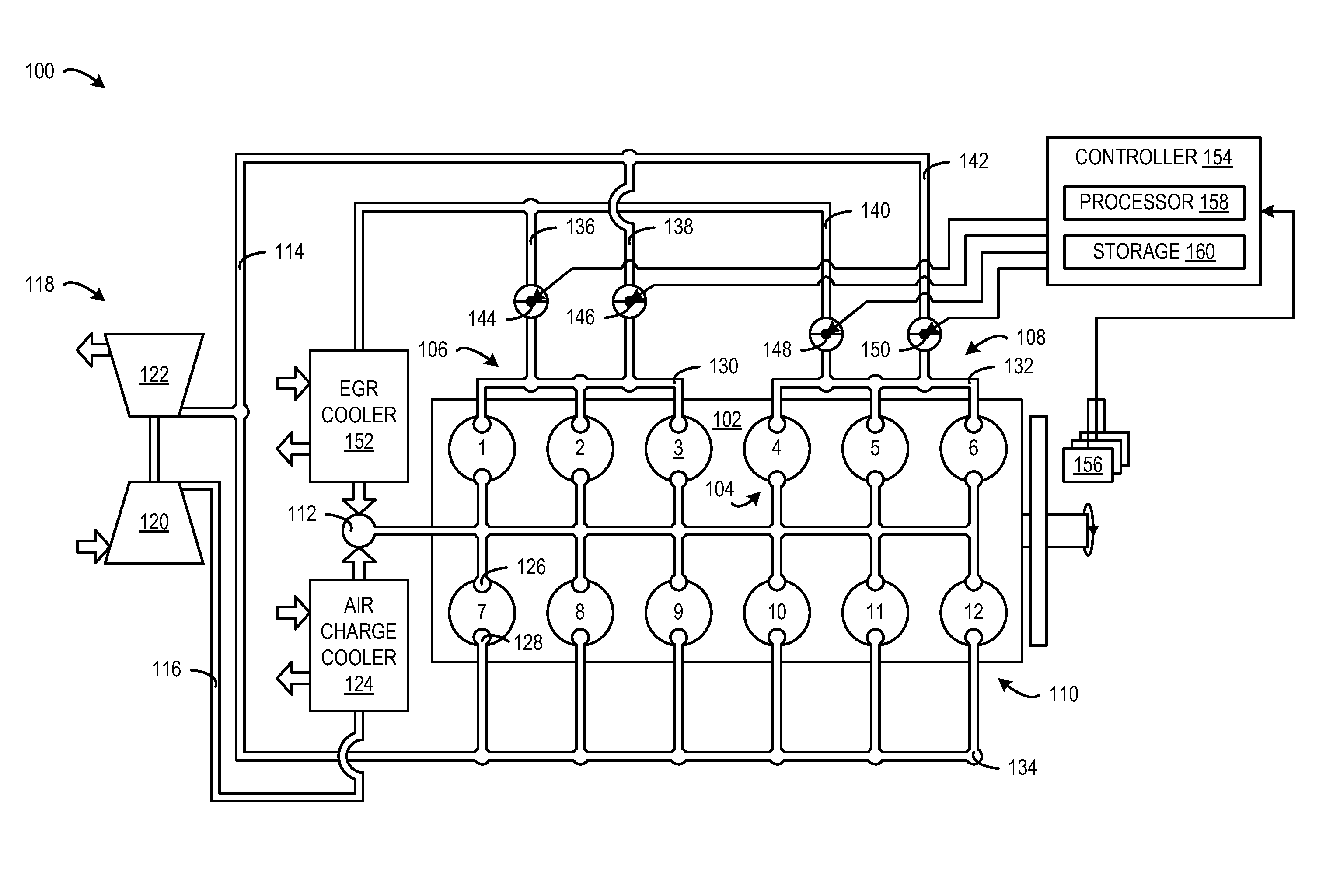
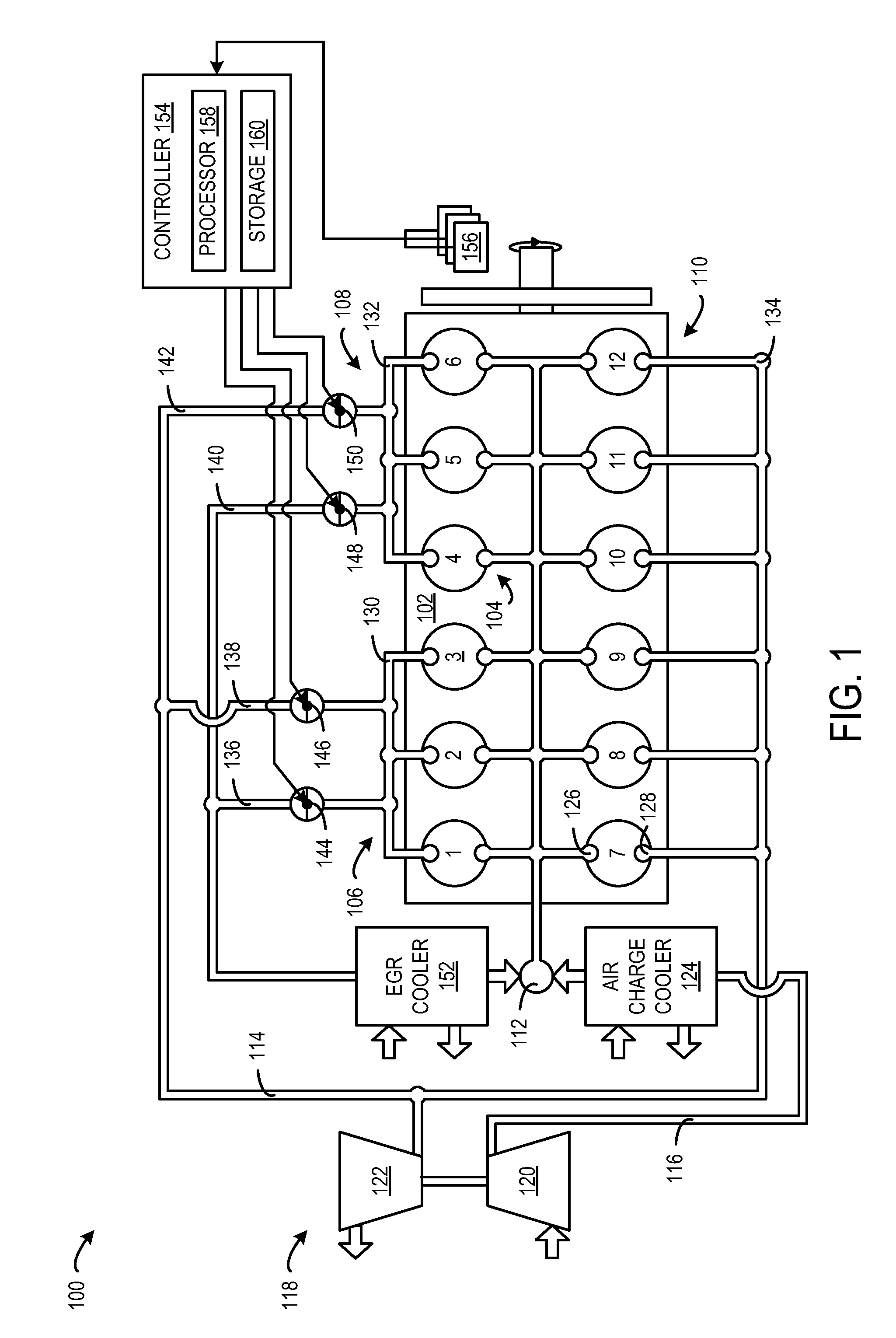
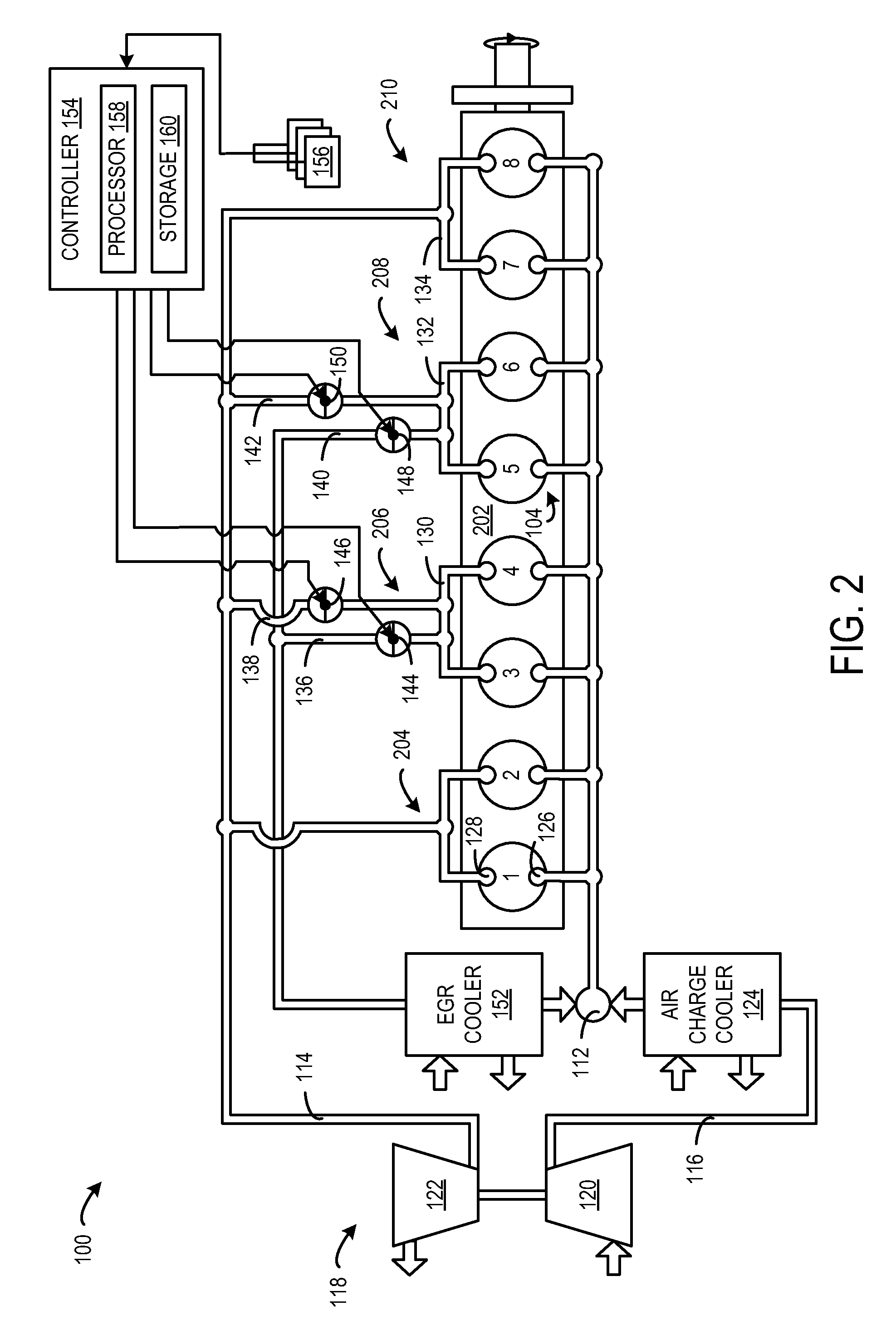
[0011]The present description relates to systems and methods for controlling EGR gas flow generated from different groups of donor cylinders of an engine. More particularly, the present description relates to selectively backpressuring only as many cylinder groups as needed to provide to a commanded EGR gas flow. In one example, an engine includes two different groups of donor cylinders. Each group of donor cylinders is equipped with EGR valves and exhaust valves that are adjustable to direct exhaust gas between an exhaust pipe and an EGR passage. The valves are controlled such that a minimum number of donor cylinder groups to provide a commanded amount of EGR are backpressured at any time.

[0012]For example, when a lower EGR gas flow is commanded, the valves of one donor cylinder group are adjusted to direct exhaust gas to the exhaust pipe so as not to create excess backpressure in that donor cylinder group, and the valves of the other donor cylinder group are adjusted or throttled ...


PUM


Abstract

Exhaust gas recirculation (EGR) systems and methods are provided. In one embodiment, a method for controlling an engine includes providing a first EGR gas flow to an intake manifold of the engine by closing a first EGR valve or a second EGR valve and at least partially opening the other of the first EGR valve and the second EGR valve, wherein the first and second EGR valves are respectively positioned in first and second EGR passages respectively coupled between first and second donor cylinder groups and an intake manifold, and providing a second EGR gas flow that is higher than the first EGR gas flow to the intake manifold by fully opening the first EGR valve or the second EGR valve and at least partially opening the other of the first EGR valve and the second EGR valve.

Description

FIELD[0001]The subject matter disclosed herein relates to exhaust gas recirculation (EGR) systems and methods, and more particularly to controlling the introduction of EGR gas into an engine intake.BACKGROUND[0002]Engines may utilize recirculation of exhaust gas from an exhaust passage to an intake manifold, a process referred to as Exhaust Gas Recirculation (EGR), to reduce regulated emissions. In one approach, one or more cylinders are dedicated to generating EGR gas that is delivered to the intake manifold for combustion. These cylinders may be referred to as donor cylinders. Correspondingly, one or more other cylinders are dedicated to generating exhaust gas that is delivered to an exhaust pipe for a turbocharger and after-treatment. These cylinders may be referred to as non-donor cylinders. One benefit of utilizing a donor cylinder EGR system is exhaust backpressure that is created from routing EGR gas to the intake manifold may be limited to only the donor cylinders, while the...

Claims


Application Information

Patent Timeline
Patent Type & Authority Patents(United States)
IPC IPC(8): F02M25/07F02B29/04F02D21/08F02D41/00
CPCF02D21/08F02D41/005F02M25/0744F02M25/0749F02D41/0077F02D41/0082F02D2021/083F02B29/0406F02M25/0727Y02T10/47F02M26/43F02M26/23F02M26/38Y02T10/40
Inventor FREUND, SEBASTIAN WALTERFRITZ, JASSINBIKAS, GEORGIOSJENKINS, SEAN
Owner GE GLOBAL SOURCING LLC
Why Eureka
Try Eureka