Carbon fiber thermal interface for cooling module assembly

a thermal interface and cooling module technology, applied in the field of battery packs, can solve the problems of affecting the operation of lithium-ion batteries, undesired effects, affecting the durability of joints, etc., and achieves the effects of minimizing manufacturing complexity, robust mechanical tolerance of assembly, and enhancing reliability

Active Publication Date: 2015-02-03
GM GLOBAL TECH OPERATIONS LLC
View PDF7 Cites 0 Cited by
  • Summary
  • Abstract
  • Description
  • Claims
  • Application Information

AI Technical Summary

Benefits of technology

[0008]In concordance with the instant disclosure, a battery cooling system that has a robust mechanical tolerance for assembly, minimizes a manufacturing complexity, enhances reliability, provides a high thermal conductivity, minimizes a need for additional components such as thermal interface material and fin feet, and eliminates a need to design a stiff heat sink for high clamping force between the heat sink and a fin foot of the battery cooling system, is surprisingly discovered.
[0009]The carbon fiber thermal interface of the present disclosure provides robust thermal conductivity and also robust mechanical integrity for cooling module assembly applications. Rovings of carbon fibers may be pre-assembled in bundles to form a brush. The brush is coupled to at least one of a cooling plate, also known as a fin, and a heat sink component to provide the thermal interface. Various stacking and attaching methods can be used to couple the cooling plate and the heat sink component with the brushes. The thermal interface may be brush-to-brush or brush-to-surface, as desired. A mechanical flexibility of the bundled carbon fibers permits robust assembly of the cooling plates in a final module stacking operation.

Problems solved by technology

When overheated or otherwise exposed to high-temperature environments, undesirable effects can impact the operation of lithium-ion batteries.
Hot joining methods can undesirably affect material microstructure, which can affect joint durability.
Known joining methods also typically require filler material such as brazing solders, welding consumables, bonding adhesives, and thermal interface materials, which can undesirably affect thermal conductivity and increase manufacturing complexity.

Method used


Image

  • Carbon fiber thermal interface for cooling module assembly
  • Carbon fiber thermal interface for cooling module assembly
  • Carbon fiber thermal interface for cooling module assembly

Examples


Embodiment Construction

[0020]The following detailed description and appended drawings describe and illustrate various embodiments of the invention. The description and drawings serve to enable one skilled in the art to make and use the invention, and are not intended to limit the scope of the invention in any manner. In respect of the methods disclosed, the steps presented are exemplary in nature, and thus, are not necessary or critical.

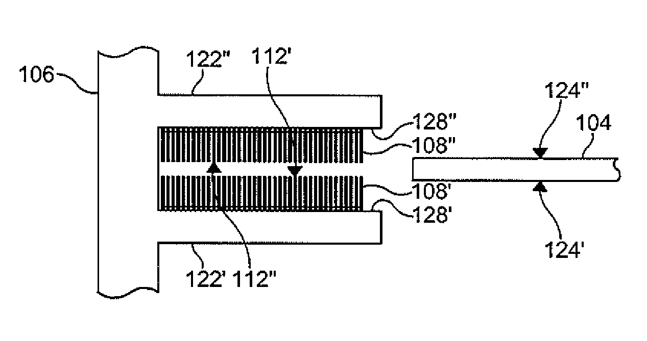
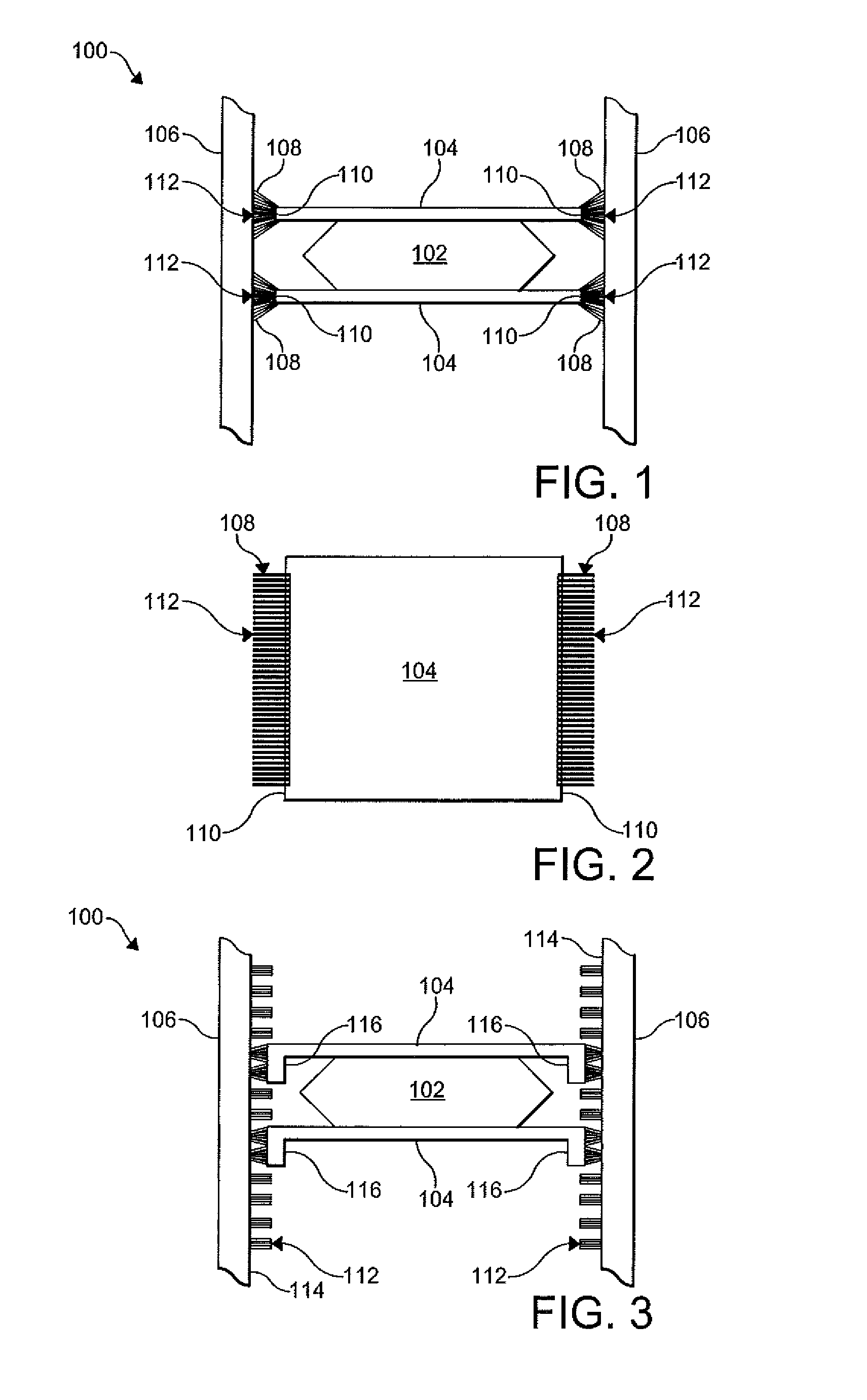
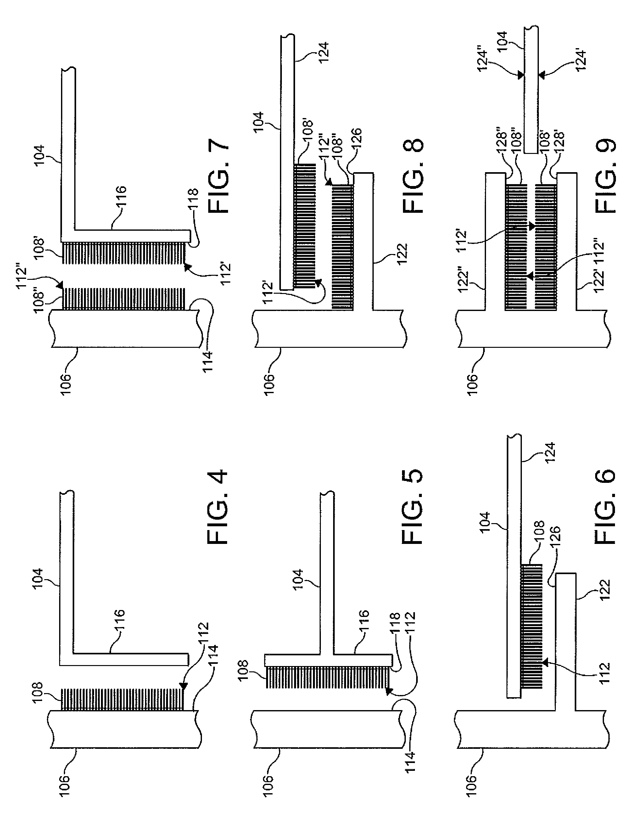
[0021]With reference to FIGS. 1-12, a cooling system 100 for a battery cell 102 is illustrated. The battery cell 102 is configured to generate power from an electrochemical reaction. The battery cell 102 may be employed in a battery pack (not shown) for a propulsion system of an electric vehicle (not shown), for example. The battery cell 102 may be a prismatic battery cell, for example, as described and shown in Assignee's Assignee's U.S. Pat. No. 8,771,382 to Heise issued Jul. 8, 2014. As a nonlimiting example, the battery cell 102 is a prismatic lithium ion (Li-ion) pouc...


PUM

PropertyMeasurementUnit
flexibleaaaaaaaaaa
axial thermal conductivityaaaaaaaaaa
radial thermal conductivityaaaaaaaaaa

Abstract

A cooling system includes a cooling plate configured to abut a battery cell. A heat sink is in thermal communication with the cooling plate by at least one carbon fiber brush, the carbon fiber brush coupled to one of the cooling plate and the heat sink and flexible at a free end.

Description

FIELD OF THE INVENTION[0001]The present disclosure relates to a battery pack and more particularly to a cooling system for the battery pack.BACKGROUND OF THE INVENTION[0002]A battery cell has been proposed as a clean, efficient and environmentally responsible power source for electric vehicles and various other applications. One type of battery cell is known as the lithium-ion battery. The lithium-ion battery is rechargeable and can be formed into a wide variety of shapes and sizes so as to efficiently fill available space in electric vehicles. For example, the battery cell may be prismatic in shape to facilitate a stacking of the battery cells. A plurality of individual battery cells can be provided in a battery pack to provide an amount of power sufficient to operate electric vehicles.[0003]Typical prismatic battery cells have a pair of plastic coated metal layers fused around a periphery of the battery cell in order to seal the battery cell components. The sealing of the battery ...

Claims


Application Information

Patent Timeline
Patent Type & Authority Patents(United States)
IPC IPC(8): H01M10/60B60K1/04H01M10/647H01M10/6551H01M10/6554
CPCH01M10/5032H01M10/5046H01M10/5053B60K1/04H01M2220/20H01M10/647H01M10/6551H01M10/6554H01M10/625Y02E60/10F28F21/02F28F2260/00
Inventor HEISE, AXELANDERSON, ALASTAIR GORDONTOEPFER, STEFAN
Owner GM GLOBAL TECH OPERATIONS LLC
Why Eureka
Try Eureka