Spectroscopic imaging probes, devices, and methods

a technology of spectroscopic imaging and probes, applied in the field of imaging probes, can solve the problems of difficult detection of collected signals relative to excitation light reflected from various optical interfaces, large size of fiber bundles, and high cost, and achieve the effect of reducing the number of optical interfaces, improving the detection efficiency, and improving the detection efficiency

Active Publication Date: 2015-02-10
LIGHTLAB IMAGING
View PDF67 Cites 80 Cited by
  • Summary
  • Abstract
  • Description
  • Claims
  • Application Information

AI Technical Summary

Benefits of technology

[0007]One embodiment of the present invention provides methods for obtaining color reflectance signals through a probe that includes one or more optical fibers. Suitable optical fibers include single-core fibers having a single cladding layer (i.e., a single clad fiber (SCF)) or multiple cladding layers (MCF) such as a dual clad fiber (DCF) which has two cladding layers.
[0008]In some embodiments, light composed of multiple wavelengths is launched (or injected) from a light source directly or indirectly (e.g., via another fiber) into the core of a dual clad fiber (DCF) fiber that is optically connected to a probe. Injected light travels down the fiber towards the probe until the injected light exits the probe and impinges on the sample. Light reflected by the sample is then collected by the probe and is transmitted back through the fiber towards the light source through the inner cladding of the DCF. Light passing back through the fiber is directed to one or more detectors that receive an optical signal or an electrical signal correlated to the optical signal. The collected signals are processed to subsequently form a colored or hyperspectral image of the sample. The signal detection or collection steps can be performed sequentially with one detector or in parallel with multiple detectors.

Problems solved by technology

However, fiber bundles often have a relatively large size, can be stiff and are generally expensive.
One technical difficulty of performing single-fiber imaging is the separation of the excitation light and the collection light.
Because the excitation light usually is much more intense than collected light, the collected signals are harder to detect relative to the excitation light reflected from various optical interfaces.
As a result, it is difficult to obtain real-time color images of the vessel wall in the visible light range using existing optical coherence tomography (OCT) systems.
OCT also typically cannot measure light produced by incoherent optic processes such as fluorescence.

Method used


Image

  • Spectroscopic imaging probes, devices, and methods
  • Spectroscopic imaging probes, devices, and methods
  • Spectroscopic imaging probes, devices, and methods

Examples


Embodiment Construction

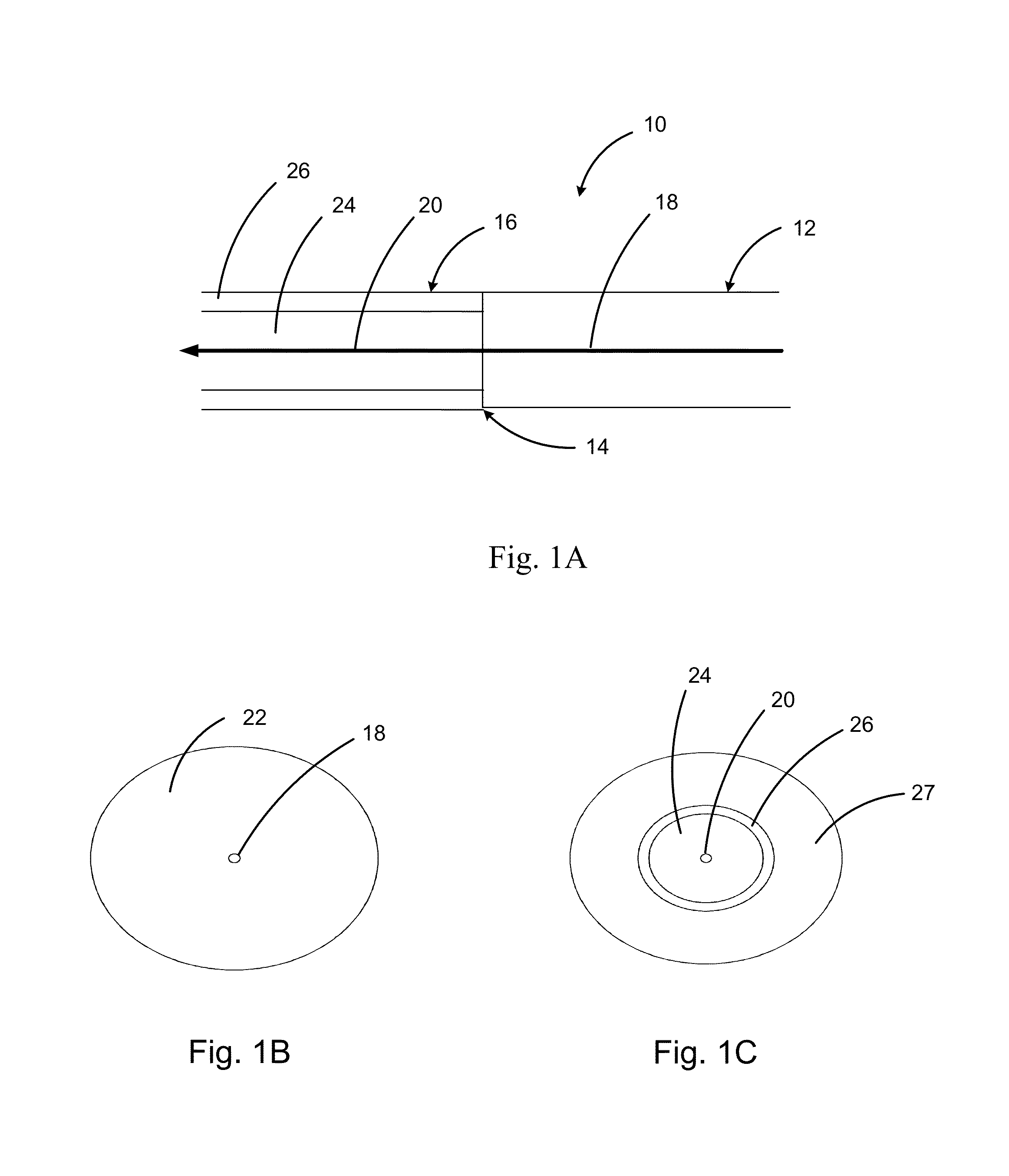
[0054]FIG. 1A shows an exemplary optical coupler 10, constructed in accordance with an illustrative embodiment of the invention. A single-clad fiber (SCF) 12 is optically coupled to a dual-clad fiber (DCF) 16. In some embodiments, excitation light injected into the core 18 of SCF 12, enters the core 20 of DCF 16, and then propagates to a rotating imaging probe at the other end of the DCF 16 (not shown). FIG. 1B shows a cross-sectional view of the SCF 12 of FIG. 1A. SCF 12 has a core 18 and a single cladding layer 22. FIG. 1C shows a cross-sectional view of the DCF 16 of FIG. 1A. DCF has a core 20, a first (or inner) cladding layer 24, a second (or outer) cladding layer 26 and a jacket 27. Typically, the diameter of the outer cladding 26 matches the diameter of the cladding 22 in the SCF because most fibers are the same size. However, variations in fiber sizes and custom fibers are possible such that the diameters of coupled fibers or cladding layers can differ.

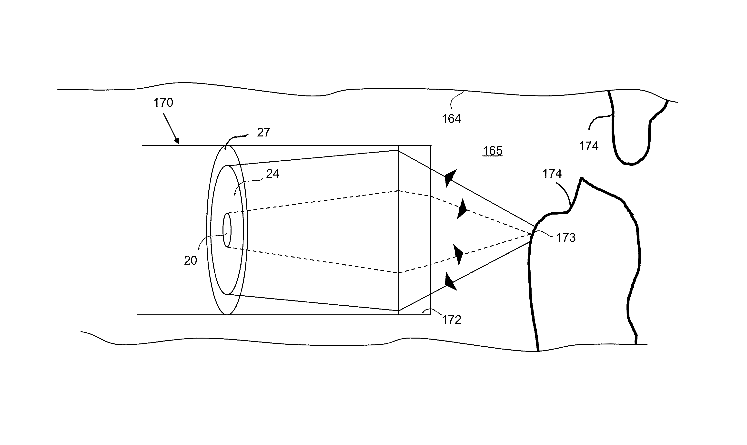
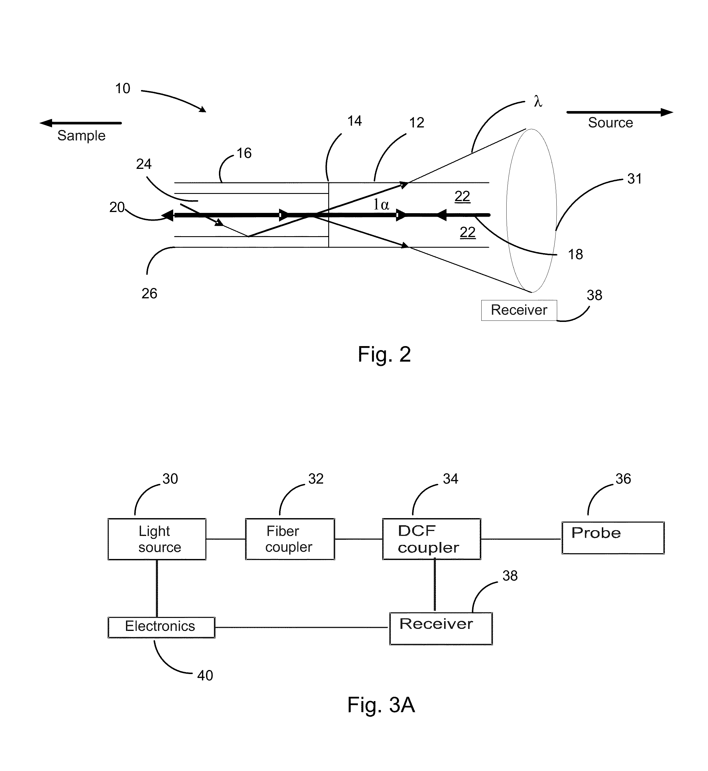
[0055]FIG. 2 shows fur...


PUM


Abstract

In part, the invention relates to a single clad fiber to multi-clad optical fiber connector for use in applying excitation light to a sample and obtaining reflected light from the sample. The connector can include a dual clad optical fiber portion and a single clad optical fiber portion in optical communication with the dual clad optical fiber portion. In one embodiment, a core of the dual clad optical fiber portion and a core of the single clad optical fiber portion have substantially similar indices of refraction. In one embodiment, excitation light is propagated by the core of the dual clad optical fiber. Further, in one embodiment, light reflected by the sample is propagated by the first cladding layer of the dual clad optical fiber portion.

Description

FIELD OF INVENTION[0001]This invention pertains generally to imaging probes and more specifically to probes having color spectroscopic imaging and tomographic capabilities suitable for use in various applications such as medical imaging, fiber-optic sensing, and industrial inspection.BACKGROUND[0002]Fiber optic sensing has been used for probing remote areas that have limited spatial clearance. It is particularly useful in biomedical research for probing internal cavities (e.g., body lumens) and in industrial applications for monitoring hard-to-reach areas such as the inside of a small curved tube. One particular area of fiber optic sensing relates to imaging. A fiber bundle can be used to transmit images coherently along the bundle. This approach is used in endoscopic applications. However, fiber bundles often have a relatively large size, can be stiff and are generally expensive.[0003]Another possible arrangement is to reconstruct an image by scanning a single fiber over a sample o...

Claims


Application Information

Patent Timeline
Patent Type & Authority Patents(United States)
IPC IPC(8): G02B6/26G02B6/00
CPCG02B6/26G02B6/00A61B5/0066G02B6/3604G02B6/4206G02B6/4214G02B6/4215G02B6/4287G02B6/262A61B5/0075A61B5/0084G02B6/264H04B10/0775
Inventor XU, CHENYANGSCHMITT, JOSEPH M.
Owner LIGHTLAB IMAGING
Why Eureka
Try Eureka