
Mining vehicle and method for its energy supply

a technology for mining vehicles and energy supply, which is applied in the field of mining vehicles, can solve the problems of mine fire safety, combustion engine requires a lot of space on the carriage of the vehicle, and combustion engine also has adverse effects on the fire safety of the mine, so as to achieve the effect of reducing the effective load of the mining vehicle and high drilling power

Active Publication Date: 2015-02-17
SANDVIK MINING & CONSTR OY
View PDF31 Cites 12 Cited by
  • Summary
  • Abstract
  • Description
  • Claims
  • Application Information

AI Technical Summary

Benefits of technology

The present invention is about a system for mining vehicles that helps to compensate for poor power transmission in the electrical network of the mining site. The system includes an electric motor for operating the main function and an auxiliary function, as well as a power-generating auxiliary unit that provides additional power during peak load situations. This helps to keep the current taken from the network lower, reducing the effective load of the mining vehicle and allowing for better control of the power supply. The system can adjust the power taken from the network or provide all the required power from the auxiliary unit, even if the network is not available for some reason. Overall, the system improves the efficiency and flexibility of mining vehicle operations.

Problems solved by technology

However, exhaust gases and noise from a combustion engine cause problems in mines.
In addition, a combustion engine requires a lot of space on the carriage of the vehicle, and necessitates regular maintenance.
A combustion engine also has adverse effects on the fire safety of the mine, since it has hot surfaces and it is also necessary to store and handle flammable fuel in the vehicle and mine.
A problem with such a mining vehicle that is fully dependent on batteries is the additional weight caused by the transported batteries.
In addition, the capacity of the batteries is quite limited, and the batteries of the mining vehicle need to be charged relatively often.

Method used


Image

  • Mining vehicle and method for its energy supply
  • Mining vehicle and method for its energy supply
  • Mining vehicle and method for its energy supply

Examples


Embodiment Construction

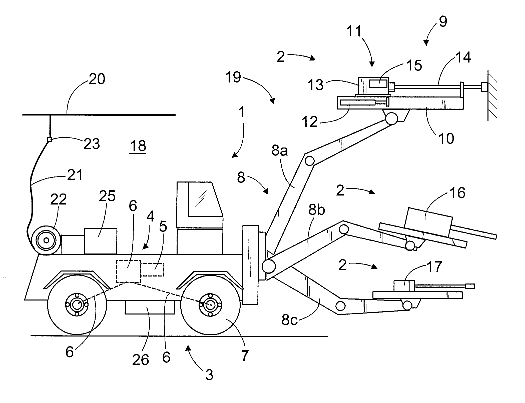
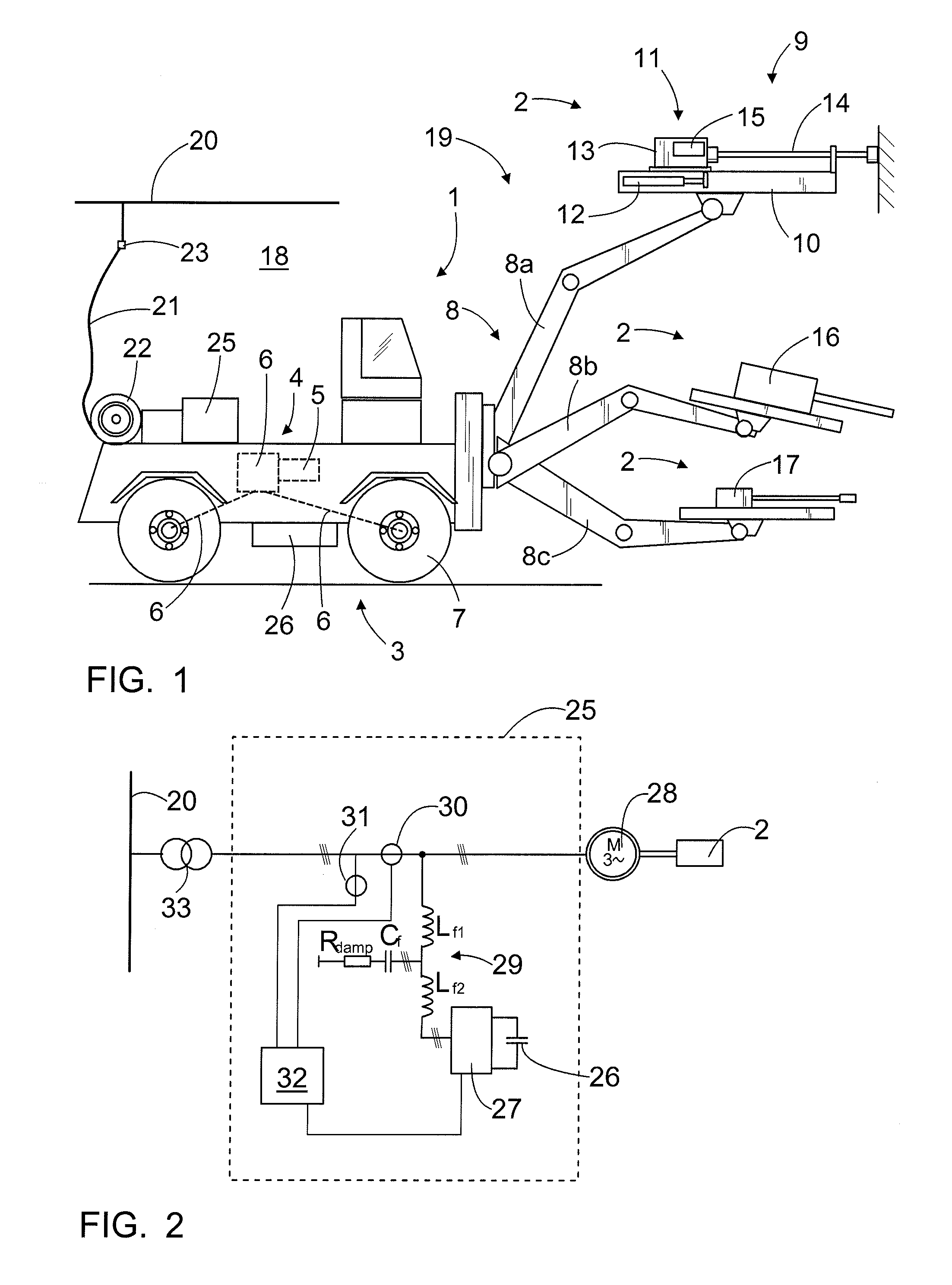
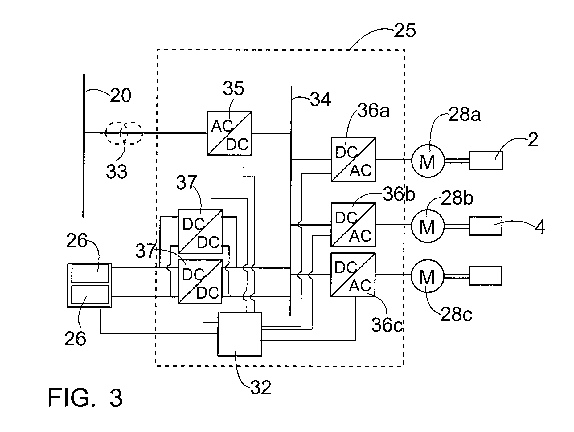
[0020]FIG. 1 shows a rock drilling rig that is one example of a mining vehicle 1 equipped with one or more mining work devices 2. The rock drilling rig comprises a carriage 3 that may be moved by means of drive equipment 4. The drive equipment 4 comprises one or more drive motors 5 and one or more power transmission means 6 for transmitting drive power to one or more wheels 7. The drive power transmission may comprise a mechanical gear system and mechanical power transmission members or, alternatively, the drive power transmission may be hydraulic or electric. There may be one or more booms 8 arranged on the carriage 3, and the boom may be equipped with a mining work device 2. In the embodiment shown in FIG. 1, the first boom 8a is a drilling boom, at the outermost end of which there is a rock drilling unit 9 comprising a feed beam 10, along which a rock drilling machine 11 may be moved by means of a feed device 12. The rock drilling machine 11 may comprise a percussion device 13 fo...


PUM

PropertyMeasurementUnit
poweraaaaaaaaaa
electrical energyaaaaaaaaaa
idle poweraaaaaaaaaa

Abstract

The invention relates to a mining vehicle and method for its energy supply. The mining vehicle has a carriage, driving equipment for moving the carriage, and at least one mining work device. Further, the mining vehicle has at least one electric motor for operating a main function of the mining vehicle, and at least one electric motor for operating an auxiliary function of the mining vehicle. The mining vehicle further has a power-generating auxiliary unit. When necessary, the power-generating auxiliary unit supplies at least part of the power required by the electric motor operating the auxiliary function.

Description

RELATED APPLICATIONS[0001]The present application is a U.S. National Phase Application of International Application No. PCT / Fl2010 / 051088 (filed 27 Dec. 2010) which claims priority to Finnish Application Nos. 20096403 (filed 28 Dec. 2009) and 20105580 (filed 25 May 2010).BACKGROUND OF THE INVENTION[0002]The invention relates to a mining vehicle with a carriage, drive equipment for moving the carriage, at least one mining work device which is one of the following: rock drilling machine, bolting device, shotcrete apparatus, scaling device, injection device, blasthole charger, loading device, measuring device; at least one electric motor for operating the main function of the mining vehicle and at least one electric motor for operating the auxiliary function of the mining vehicle.[0003]The invention further relates to a method for the energy supply of a mining vehicle with a carriage, drive equipment for moving the carriage, at least one mining work device which is one of the following...

Claims


Application Information

Patent Timeline
Patent Type & Authority Patents(United States)
IPC IPC(8): B60L1/00B60M1/12B60K1/00B60L9/12B60L9/18B60L11/18E21B7/02
CPCB60L9/18B60L9/12B60L11/1801B60L11/1811E21B7/025B60L11/18B60K1/00B60L2200/40B60L2210/10B60Y2200/412B60Y2200/49Y02T10/7005Y02T10/7088Y02T10/7216Y02T90/127Y02T90/14B60L1/003B60L9/24B60L50/53B60L53/20H02J7/345Y02T10/70Y02T10/7072Y02T10/72Y02T90/12
Inventor OSARA, JUKKAKOUVO, MIKKOPIIPPONEN, JUHA
Owner SANDVIK MINING & CONSTR OY
Learn More