Cone beam CT scanning

a computerized tomography and cone beam technology, applied in the field of cone beam computerized tomography, can solve the problems of increasing the reconstruction error with increasing the beam cone angle, the data sets (projections) associated with such a trajectory are theoretically insufficient for precise object reconstruction, and the estimation of object density values may not be adequate by approximation algorithms

Inactive Publication Date: 2015-02-24
EIN GAL MOSHE
View PDF3 Cites 149 Cited by
  • Summary
  • Abstract
  • Description
  • Claims
  • Application Information

AI Technical Summary

Benefits of technology

[0016]There is also provided in accordance with a non-limiting embodiment of the invention, a method for CBCT including emitting a cone beam of radiation from a radiation source in a beam direction towards an object, detecting the cone beam of radiation with a detector, moving the radiation source and the object according to a scanning trajectory, and operating the radiation source according to a sampling pattern that includes intersections of the scanning trajectory and a reconstruction trajectory, wherein motion of the radiation source is substantially confined to a spherical shell, wherein a center of the sphere substantially coincides with a center of the detector, and wherein the beam direction substantially intersects the detector center, and wherein the radiation source is moved at speed higher than a highest speed of the object by a factor of at least 10, and wherein a largest angular discrepancy between any vector in a range of the scanning trajectory and a nearest sample of the scanning trajectory does not exceed 10°, preferably 6° and more preferably 3°.

Problems solved by technology

Data sets (projections) associated with such a trajectory are theoretically insufficient for precise object reconstruction.
Such approximate algorithms may not be adequate for estimating object density values with sufficient precision required for radiotherapy treatment planning.
Reconstruction error increases with increased beam cone angle.
Consequently, the associated sampling patterns are uniquely related to the respective trajectories such that reconstruction algorithms designed for a particular trajectory cannot be used for another—the respective sampling patterns are too different.

Method used


Image

  • Cone beam CT scanning
  • Cone beam CT scanning
  • Cone beam CT scanning

Examples


Embodiment Construction

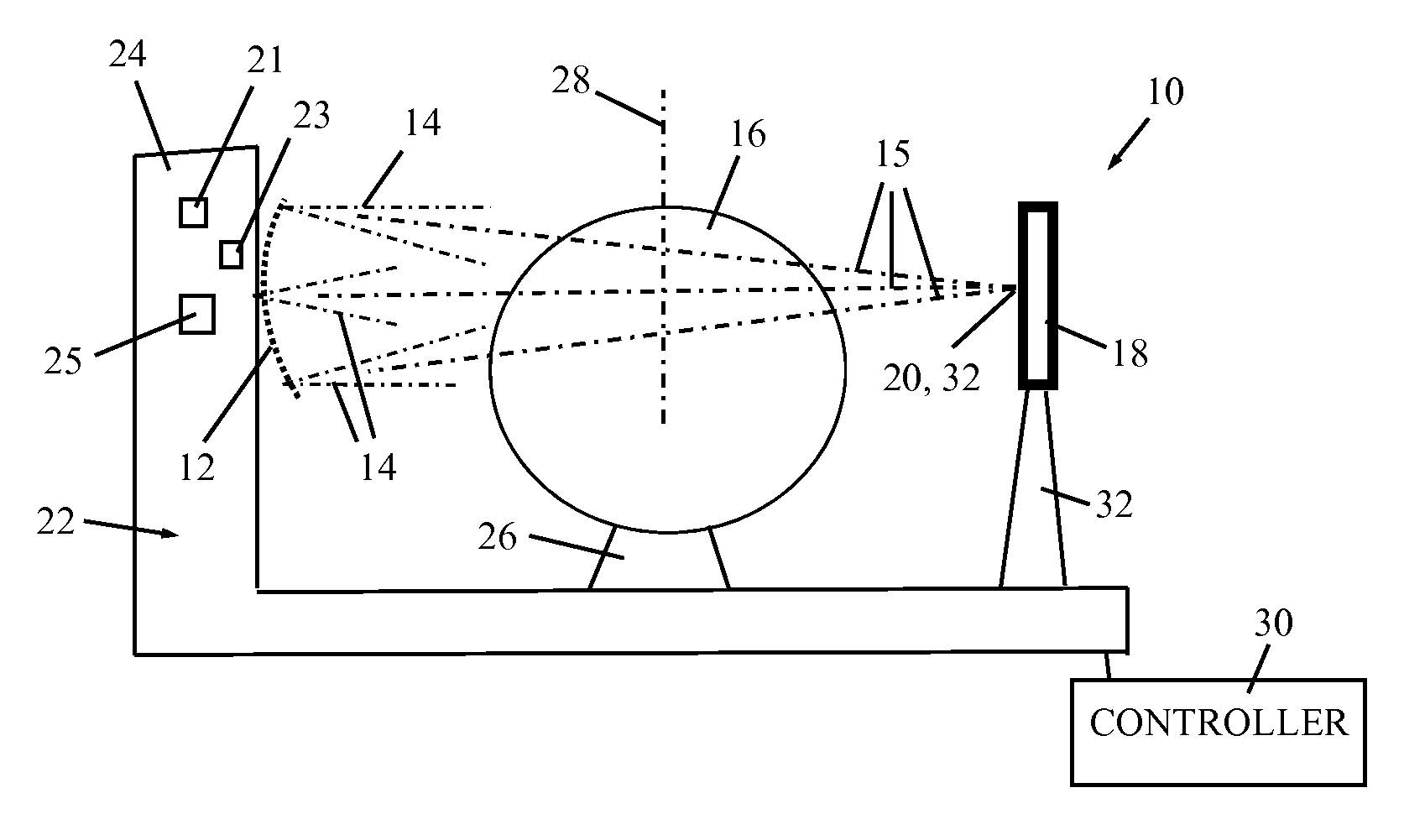
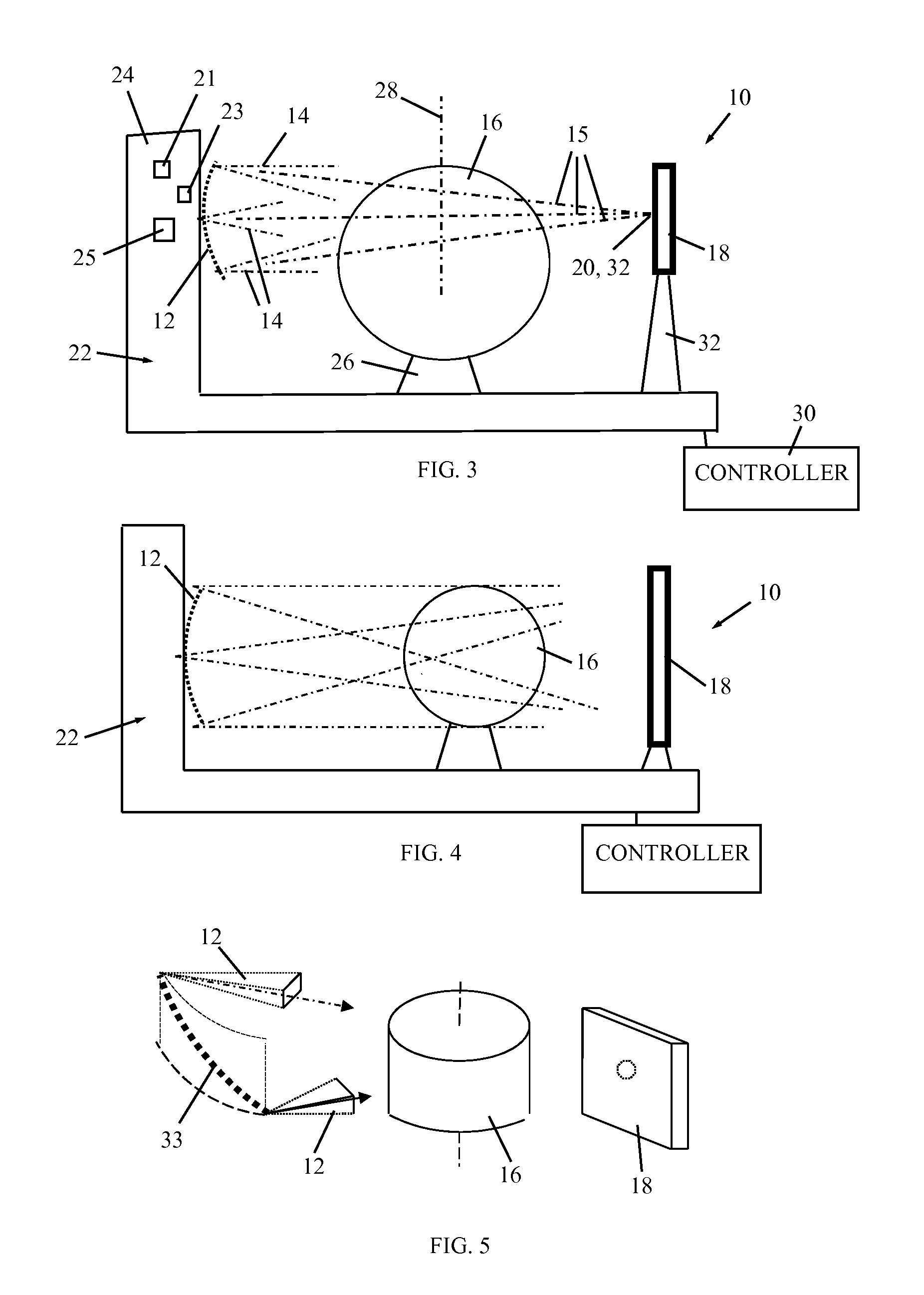
[0025]Reference is now made to FIG. 3, which illustrates a cone beam CT (CBCT) scanner system 10, constructed and operative in accordance with an embodiment of the present invention.

[0026]CBCT system 10 includes a radiation source 12 (such as, but not limited to, an X-ray source) that emits a cone beam 14 of radiation in a beam direction 15 towards an object 16, such as an animate object (e.g., human or animal) or an inanimate object. A detector 18 is provided on the other side of object 16 and has a detector center 20. Detector 18 detects the cone beam(s) 14 of radiation, which pass through, off, over or around object 16.

[0027]CBCT system 10 includes a positioner 22 that can move radiation source 12 and the object 16 according to a scanning trajectory. Without limitation, positioner 22 includes a gantry 24, which moves the housing which houses the radiation source 12. Motion of the source housing may be implemented by electronically moving the source position. To achieve that, gant...


PUM

PropertyMeasurementUnit
fan anglesaaaaaaaaaa
speedaaaaaaaaaa
trajectoryaaaaaaaaaa

Abstract

A CBCT system is described that includes a radiation source for emitting a cone beam of radiation in a beam direction towards an object, a detector for detecting the cone beam of radiation, and a positioner for moving the radiation source and the object according to a scanning trajectory. The system is operated according to a sampling pattern that includes intersections of the scanning trajectory and a reconstruction trajectory, wherein motion of the radiation source is substantially confined to a spherical shell. The positioner moves the radiation source at a speed higher than a highest speed of the object by a factor of at least 10. The largest angular discrepancy between any vector in a range of the scanning trajectory and the nearest sample of the scanning trajectory does not exceed 10°, preferably 6° and more preferably 3°.

Description

FIELD OF THE INVENTION[0001]The present invention generally relates to a method and system for cone beam computerized tomography (CBCT).BACKGROUND OF THE INVENTION[0002]Cone beam CT projections of an object are a function of scanning trajectory, that is, the relative positions of the irradiating source and the object. Generally, such a trajectory includes rotation about a rotational axis intersecting the object, similar to conventional CT. Of particular interest is imaging of a quasi-short object, which is the reconstruction of a short portion of a long object from longitudinally truncated cone beam data.[0003]In a spherical coordinate system, the two angular coordinates of a trajectory sample, i.e., the angle in the fan direction (Phi—φ) and the cone direction (Theta—θ) can be viewed as a 2D vector in a Phi / Theta plane, and respective ranges of Phi and Theta define the trajectory range.[0004]FIG. 1 illustrates examples of prior art scanning trajectories in terms of (φ, θ) coordinat...

Claims


Application Information

Patent Timeline
Patent Type & Authority Patents(United States)
IPC IPC(8): G01V5/00G01N23/04
CPCG01N23/046A61B6/027A61B6/032A61B6/4085G01N2223/3301
Inventor EIN-GAL, MOSHE
Owner EIN GAL MOSHE
Why Eureka
Try Eureka