Control apparatus for linear motor, and linear motor apparatus

a technology of control apparatus and linear motor, which is applied in the direction of motor/generator/converter stopper, dynamo-electric gear control, motor/generator/converter stopper, etc., can solve the problems of increasing the manufacturing cost of linear motor and increasing the length of linear scale, so as to improve the positioning accuracy of linear motor

Active Publication Date: 2015-03-03
THK CO LTD
View PDF33 Cites 6 Cited by
  • Summary
  • Abstract
  • Description
  • Claims
  • Application Information

AI Technical Summary

Benefits of technology

[0011]According to the present invention, it is possible to improve a positioning accuracy of a linear motor without using a linear scale.

Problems solved by technology

However, when a mover of the linear motor has a long range of motion, it is necessary to increase the length of the linear scale.
Therefore, the manufacturing cost of the linear motor is increased.

Method used


Image

  • Control apparatus for linear motor, and linear motor apparatus
  • Control apparatus for linear motor, and linear motor apparatus
  • Control apparatus for linear motor, and linear motor apparatus

Examples


first embodiment

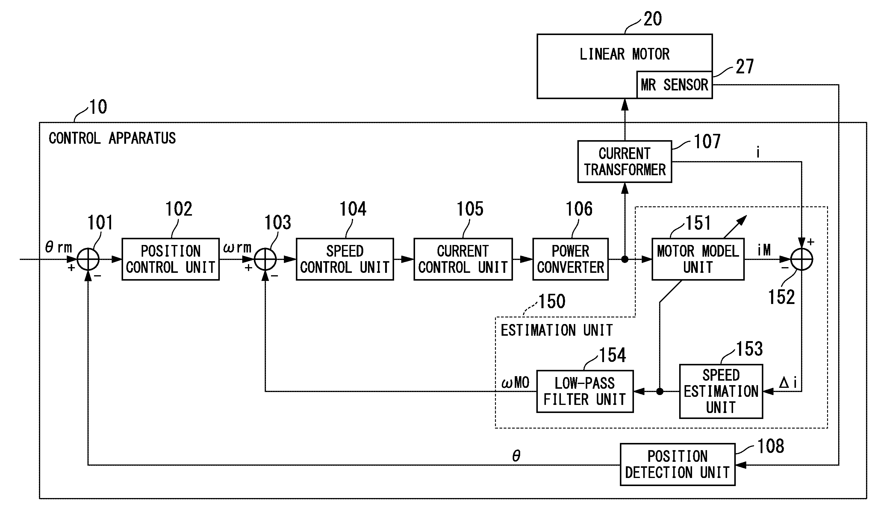
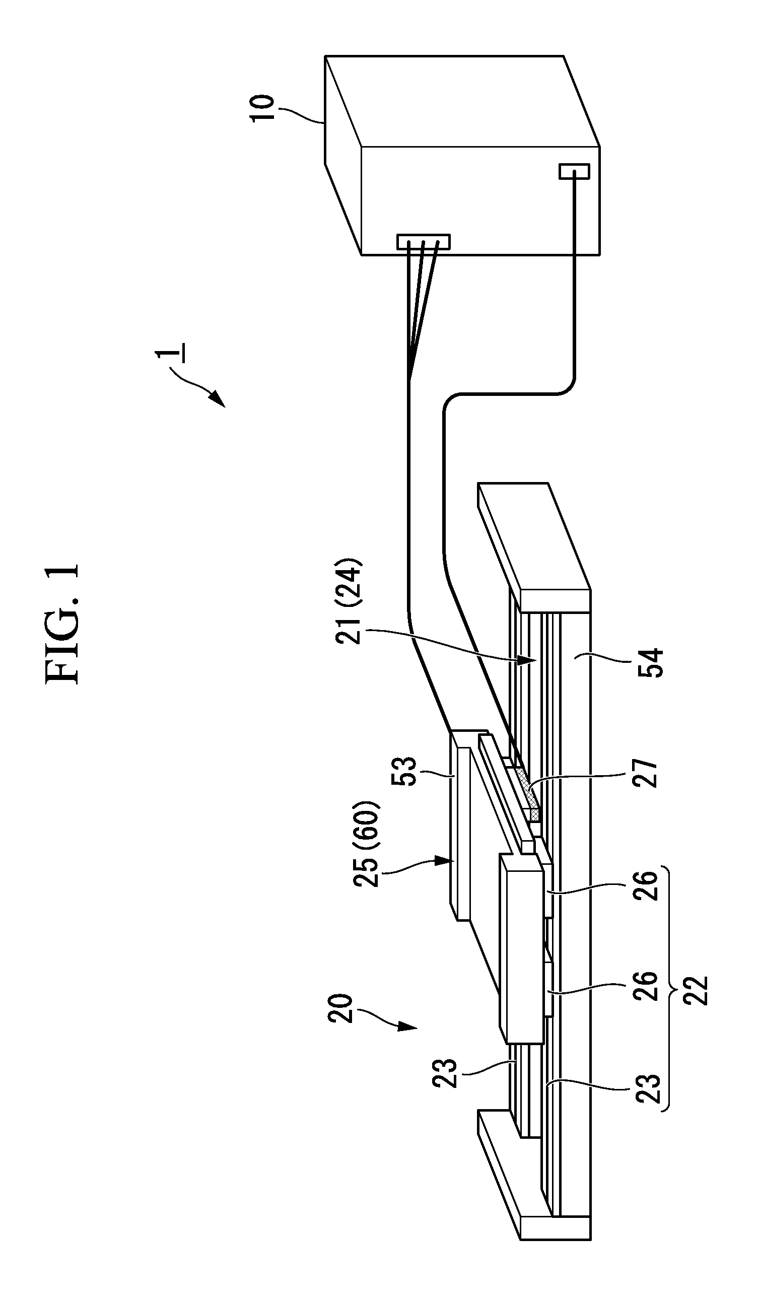
[0021]FIG. 1 is a schematic view showing a linear motor apparatus 1 of a first embodiment. The linear motor apparatus 1 has a control apparatus 10 and a linear motor 20. The control apparatus 10 is an apparatus which performs control to drive the linear motor 20. The linear motor 20 is provided with a long stator 21, a mover 25 which moves on the stator 21, and a pair of guide apparatuses 22, 22 on which the stator 21 and the mover 25 are mounted.

[0022]The guide apparatus 22 is composed of a track rail 23 and a slide block 26 which are assembled with balls interposed therebetween. The track rail 23 of the guide apparatus 22 is fixed to a base 54 of the stator 21. The slide block 26 of the guide apparatus 22 is fixed to the mover 25. Accordingly, the mover 25 is freely guided along the track rail 23 on the stator 21.

[0023]The stator 21 is provided with a plurality of drive magnets 24 arranged between the pair of track rails 23, 23. A plurality of the drive magnets 24 are arranged so ...

second embodiment

[0079]FIG. 8 is a schematic block diagram showing a configuration of a control apparatus 11 for a linear motor 20 of a second embodiment. The control apparatus 11 of the second embodiment is different from the control apparatus 10 of the first embodiment in that a speed calculation unit 111 and a speed selection unit 112 are provided.

[0080]Hereinafter, the speed calculation unit 111 and the speed selection unit 112 are described. In addition, other configurations which are the same as those in the first embodiment are denoted by the same reference signs and descriptions thereof are omitted.

[0081]The speed calculation unit 111 calculates a moving speed of the mover 25 from a change per unit hour of the detection position θ which is detected by the position detection unit 108.

[0082]The speed selection unit 112 selects any one of the estimation speed ωMO which is output from the low-pass filter unit 154 of the estimation unit 150 and the moving speed which is calculated by the speed ca...


PUM


Abstract

A control apparatus (10) includes a position detection unit (108) which detects a position of a mover of a linear motor (20) based on a change in an output signal from a magnetic sensor (27), a position control unit (102) which calculates a speed command value based on the position of the mover detected by the position detection unit (108) and a position command value of an external input, an estimation unit (150) which estimates a moving speed of the mover from a current value of a current flowing to a plurality of coils of the linear motor (20), a speed control unit (104) which calculates a current command value based on the speed command value and the estimated moving speed, and a power converter (106) which supplies power to the plurality of coils according to the current command value.

Description

TECHNICAL FIELD[0001]The present invention relates to a control apparatus for a linear motor, and a linear motor apparatus.[0002]Priority is claimed on Japanese Patent Application No. 2010-220726, filed Sep. 30, 2010, the content of which is incorporated herein by reference.BACKGROUND ART[0003]In the positioning control of a linear motor, a linear scale is used to increase a positioning accuracy. However, when a mover of the linear motor has a long range of motion, it is necessary to increase the length of the linear scale. In addition, it is also necessary to use a linear scale having less distortion. Therefore, the manufacturing cost of the linear motor is increased.[0004]Accordingly, a linear scale is only mounted in a range of motion in which positioning control is needed, so that the manufacturing cost is reduced (Patent Literature 1).[0005]In addition, the magnetism of a drive magnet of a linear motor is detected using an MR sensor attached to a mover and a position of the mov...

Claims


Application Information

Patent Timeline
Patent Type & Authority Patents(United States)
IPC IPC(8): H02P25/06H02K41/03
CPCH02K7/08H02K29/08H02K41/031H02P25/06H02P23/18
Inventor INOUE, MASASHI
Owner THK CO LTD
Why Eureka
Try Eureka