Pneumatic brake actuator with flow insensitive two way control valve

a two-way control valve and pneumatic brake technology, which is applied in the direction of braking systems, machines/engines, braking components, etc., can solve the problems of high undesirable pressure build-up in the spring chamber upon the release of the brake, increased pressure in the spring chamber, and exacerbated undesirable effects of pressure build-up in the spring chamber. , to achieve the effect of preventing direct exposure and preventing pressure build-up

Active Publication Date: 2015-03-17
HALDEX BRAKE PROD CORP
View PDF19 Cites 14 Cited by
  • Summary
  • Abstract
  • Description
  • Claims
  • Application Information

AI Technical Summary

Benefits of technology

[0020]Preferably, movement of the seal is not dependent on the rate of flow of fluid or pressure differential between the spring chamber and the service brake pressure chamber. The control valve is preferably a pilot operated valve where the pilot pressure is the pressure in the service brake pressure chamber. Preferably, the control valve includes a valve body and the seal is placed within a channel formed in the valve body. When the seal is in its open position, fluid can flow through the channel between the service brake pressure chamber and spring chamber, and when the seal is in its closed position, the channel is blocked. Preferably, the valve chamber is enclosed by the seal and the valve body. The valve chamber may also be vented to the atmosphere. Preferably, a spring biases the seal to its open position. However, it is within the scope of the invention for the seal to be constructed from a material and in a manner that it biases itself to its open position. Alternatively, the pressure in the valve chamber may bias the seal to its open position. The spring chamber is preferably sealed to prevent direct exposure to the atmosphere and common environmental contaminants.
[0021]Biasing the control valve to its open position allows air exchange between the spring chamber and the service brake pressure chamber when the service brake pressure chamber is not pressurized. When in its open position, the control valve prevents pressure build-up and vacuum creation in the spring chamber. This allows the spring brake actuator, in a sealed cavity, to be operated without the need for higher spring force to overcome vacuum formation in the spring chamber. The seal is preferably biased to its open position with enough force to overcome a negative pressure differential between the spring chamber and valve chamber that would occur in a sealed spring chamber as the volume of the spring chamber increases during actuation of the spring brake actuator, which prevents vacuum formation in the spring chamber. The control valve seal closes when the pressure in the service brake pressure chamber reaches a threshold level to prevent pressurization of both the service brake pressure chamber and the spring chamber. Because movement of the seal is not dependent on the rate of flow of fluid between the service brake pressure chamber and spring chamber, it closes and prevents fluid from entering the spring chamber when the service brakes are applied slowly.

Problems solved by technology

One known problem in association with spring brake actuators of this design is that as the large force compression spring is compressed, the pressure chamber increases in volume and the spring chamber decreases in volume, resulting in a pressure increase in the spring chamber.
The build-up of pressure in the spring chamber upon the release of the brake is highly undesirable in that any pressure build-up in the spring chamber must be offset by an increased pressure in the pressure chamber in order to fully compress the spring and thus fully release the brake.
The undesirable effects of pressure build-up in the spring chamber are exacerbated due to the fact that most pressurized air systems for heavy-duty vehicles operate at an industry standard maximum pressure.
If the combined pressure of the spring and the air pressure in the spring chamber approach that maximum pressure then the emergency brake can fail to release, only partially release, or release very slowly, all of which are undesirable.
These vent holes are undesirable because they expose the interior of the spring chamber to external environmental elements such as dirt, salt, and water, which accelerate abrasion, corrosion, or wear on the various internal brake components such as the spring.
The damage to the internal brake components by environmental elements can require increased maintenance or cause premature failure of the spring.
The filtered vent openings, however, inherently permit external air to enter the brake, yielding a brake that is not completely sealed.
Additionally, the filters require increased maintenance because they must be cleaned and / or replaced and typically do not effectively prevent water from entering the spring chamber.
An additional problem with directly externally venting the spring chamber is that the types of vehicles on which the actuator is mounted, such as tractor trailers, are often parked for extended periods in a dock bay.
Although the water is normally expelled from the spring chamber through the vent openings as the brake is released, the flooding can accelerate corrosion and introduce other environmental hazards.
Further, if it is below freezing, the water can freeze and prevent release of the brake.
Filtered vent openings do not prevent water from flooding the spring chamber.
However, when the spring brake is applied and the volume of the spring chamber increases, the one-way valve remains in its closed position and does not allow air to flow from the service brake pressure chamber into the expanding spring chamber.
Conventional two-way control valves, however, are flow rate sensitive, which means that they will only close due to increased pressure in the service brake pressure chamber if the flow of fluid into the service brake pressure chamber and through the valve reaches a certain level.
This results in application of both the service brake and the spring brake which subjects the brake system's components to increased levels of force that may cause damage.

Method used


Image

  • Pneumatic brake actuator with flow insensitive two way control valve
  • Pneumatic brake actuator with flow insensitive two way control valve
  • Pneumatic brake actuator with flow insensitive two way control valve

Examples


Embodiment Construction

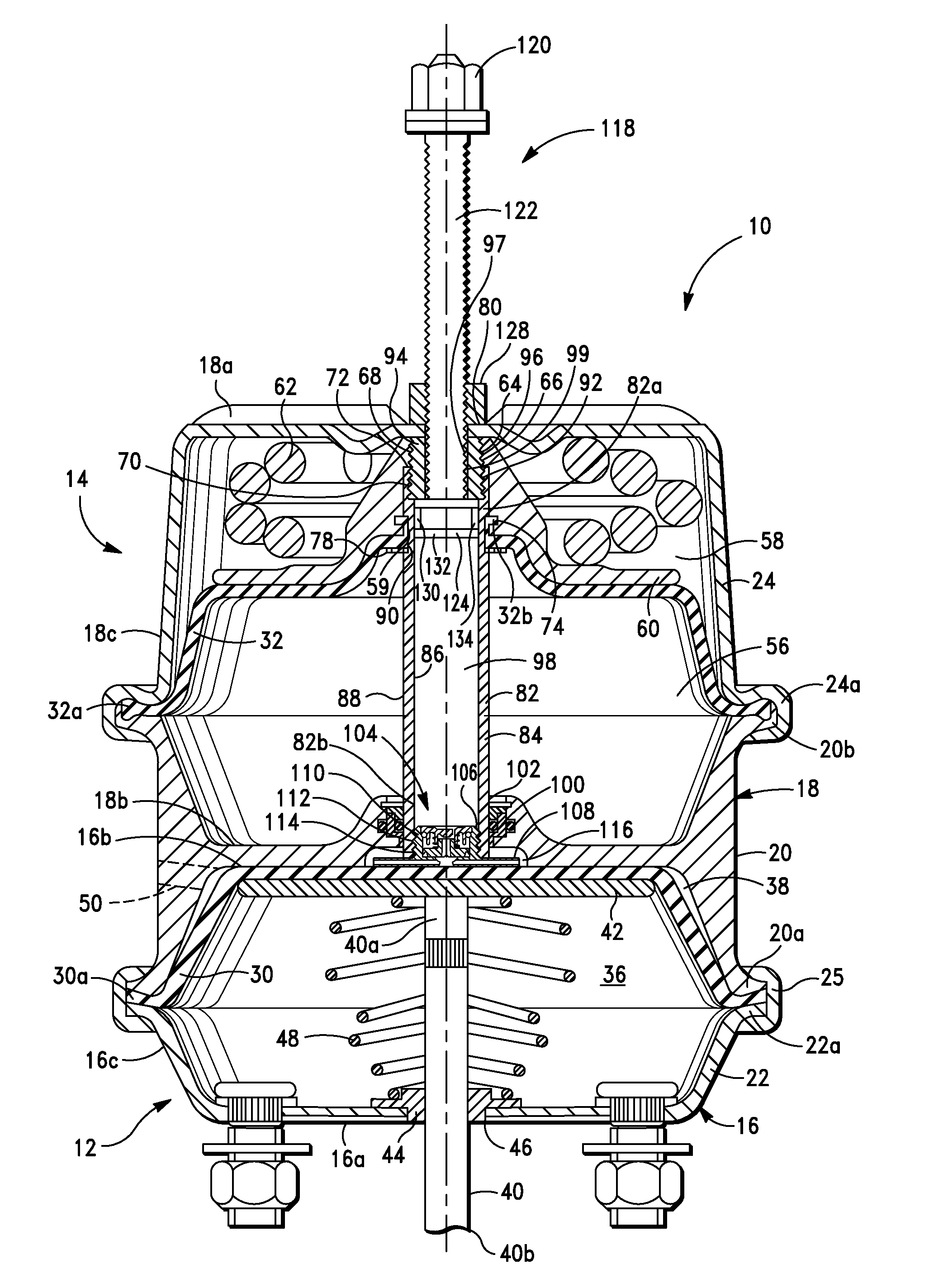
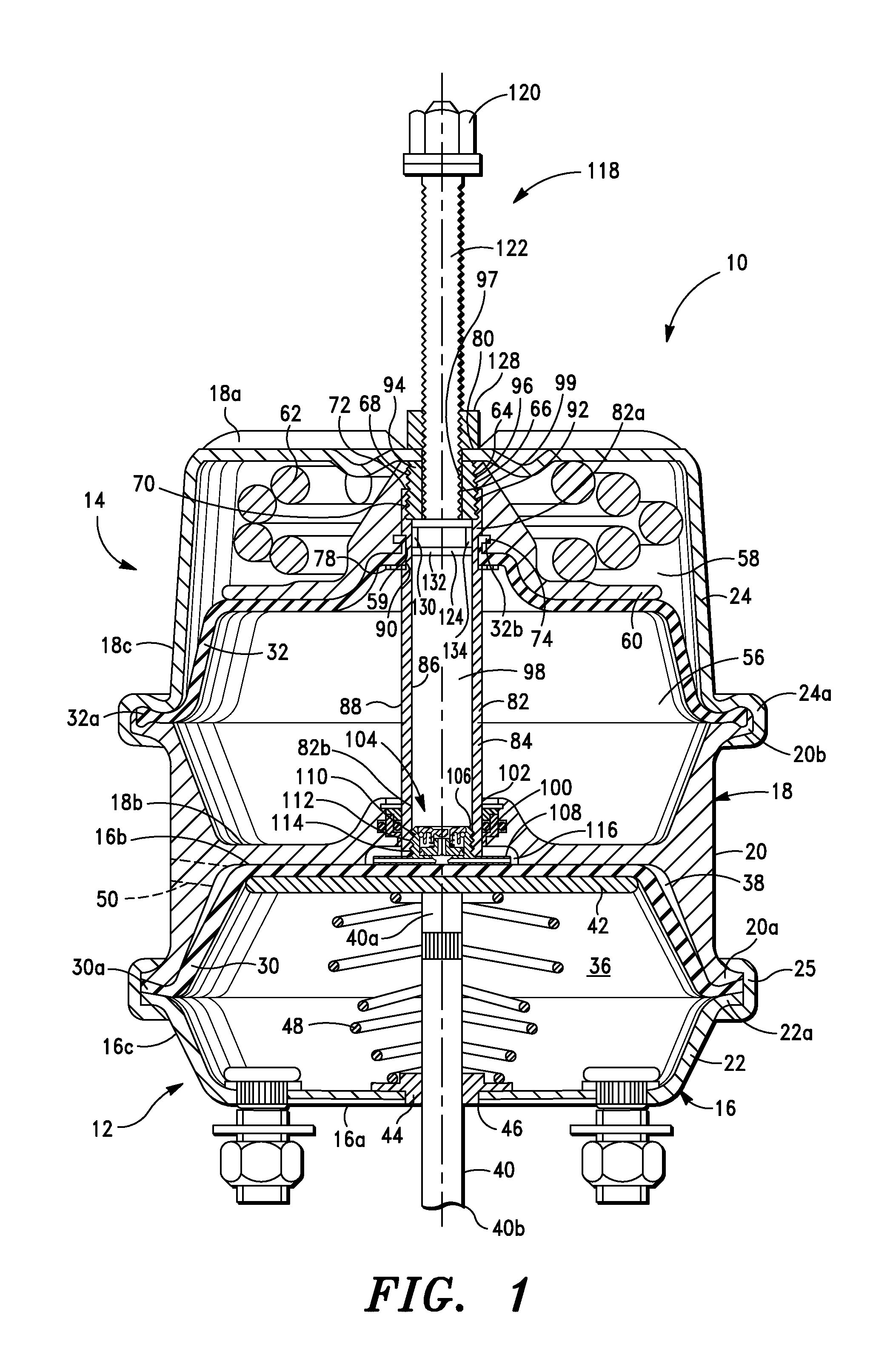
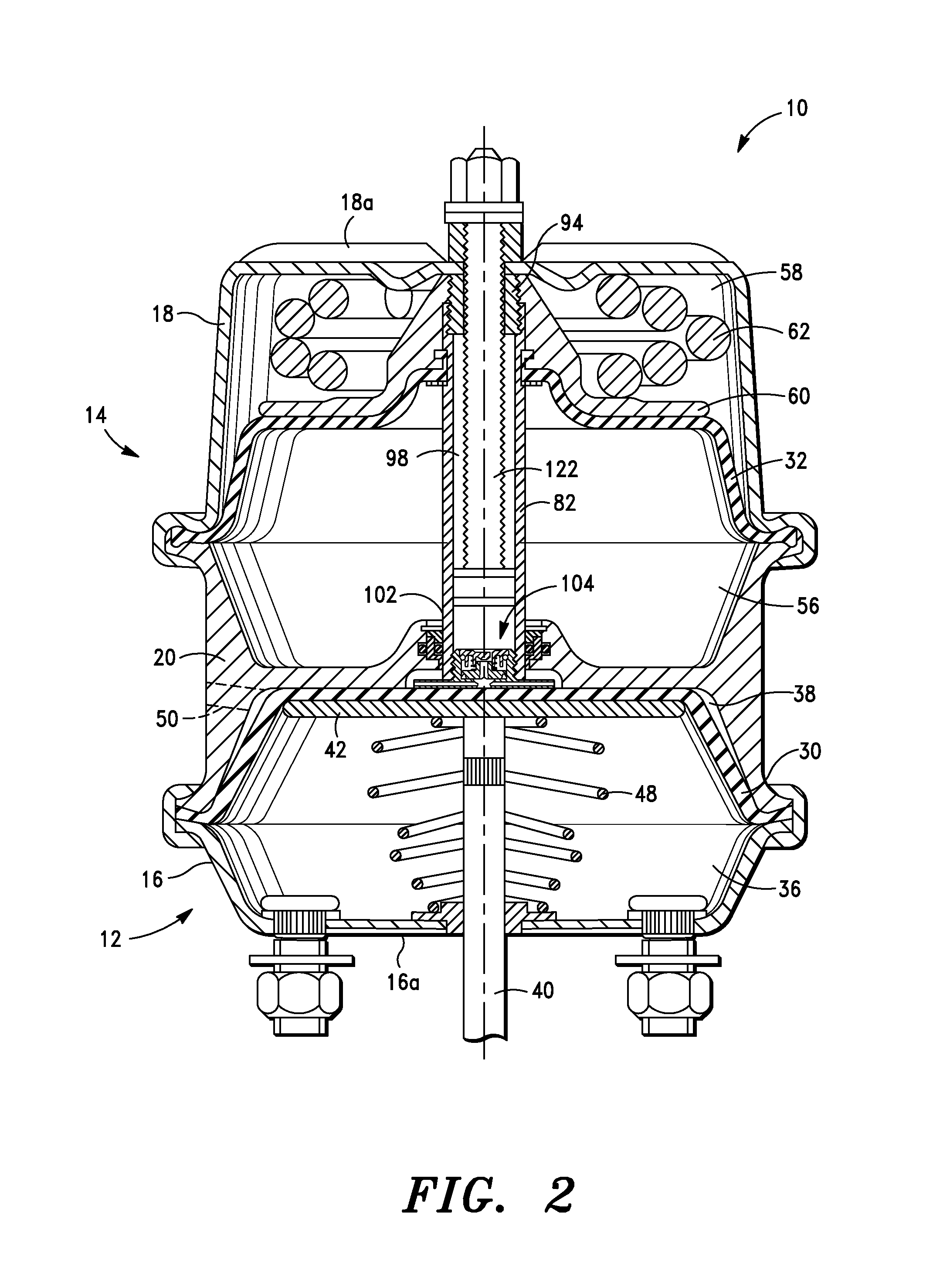
[0058]FIGS. 1-4 show a tandem-type pneumatic brake actuator 10 comprising a service brake actuator 12 in combination with a spring brake actuator 14. The service brake actuator 12 applies and releases the service or operating brakes of a vehicle. The spring brake actuator 14 is used to apply the emergency or parking brakes of the vehicle.

[0059]The service brake actuator 12 includes a housing 16 having first and second end walls 16a and 16b and a side wall 16c that is joined with and extends between the end walls 16a and 16b. The spring brake actuator 14 includes a sealed housing 18 having first and second end walls 18a and 18b and a side wall 18c that is joined with and extends between the end walls 18a and 18b. The housings 16 and 18 are formed by an adapter housing 20 that is coupled with a service brake cover 22 and a spring brake cover 24. The adapter housing 20 and spring brake cover 22 have mating flanges 20a and 22a, respectively, that are clamped together with a clamp 25 to ...


PUM


Abstract

A pneumatic brake actuator has a spring brake actuator with spring and spring brake pressure chambers, and a service brake actuator with service brake pressure and pushrod chambers. A control valve has a seal that is moveable between an open position and a closed position for regulating fluid flow between the spring chamber and service brake pressure chamber. A first surface of the seal is in fluid communication with the service brake pressure chamber and a second surface of the seal is in fluid communication with a valve chamber that is not in fluid communication with the service brake pressure chamber or spring chamber. The seal moves between its open and closed positions based on a pressure in the service brake pressure chamber. Movement of the seal is not dependent on the rate of flow of fluid between the spring chamber and the service brake pressure chamber.

Description

CROSS-REFERENCE TO RELATED APPLICATIONS[0001]Not applicable.STATEMENT REGARDING FEDERALLY SPONSORED RESEARCH OR DEVELOPMENT[0002]Not applicable.BACKGROUND OF THE INVENTION[0003]1. Field of the Invention[0004]The present invention is directed generally to pneumatic brake actuators, and more specifically to a pneumatic brake actuator with a two-way control valve.[0005]2. Description of Related Art[0006]A pneumatic brake system for a large, heavy-duty vehicle such as a bus, truck, semi-tractor, or trailer typically includes a brake shoe and drum assembly which is actuated by an actuator that is operated by the selective application of compressed air. Conventional pneumatic spring brake actuators have both a service brake actuator for actuating the brakes under normal driving conditions by the application of compressed air and a spring-type emergency brake actuator which actuates the brakes when air pressure has been released from a pressure chamber. The emergency brake actuator, or spr...

Claims


Application Information

Patent Timeline
Patent Type & Authority Patents(United States)
IPC IPC(8): F16D65/14
CPCB60T17/083F16D65/28F16D2121/10F16D2121/08F16D2123/00B60T13/38B60T13/58F16D2121/14
Inventor BRADFORD, AARON C.FISHER, ALBERT D.
Owner HALDEX BRAKE PROD CORP
Why Eureka
Try Eureka