Turbine engine fan comprising a balancing system with blind holes for accommodating masses

a technology of balancing system and turbine engine, which is applied in the direction of vessel construction, marine propulsion, combustion air/fuel air treatment, etc., can solve the problems of reducing the performance of the turbine engine, and reducing the number of balancing screws. , the effect of reducing the mass of the balancing system

Active Publication Date: 2015-03-24
SN DETUDE & DE CONSTR DE MOTEURS DAVIATION S N E C M A
View PDF6 Cites 12 Cited by
  • Summary
  • Abstract
  • Description
  • Claims
  • Application Information

AI Technical Summary

Benefits of technology

[0017]Thus, the fact that the mass accommodation holes are concealed by the intake cone, and no longer provided as through-holes in the latter, advantageously implies that the outer surface for defining the vein no longer has mass accommodation recesses as described earlier in connection with the embodiments of the prior art. The airflow on the intake cone is therefore optimized, which globally generates a reduction in drag, and therefore an increase in the performances of the turbine engine.
[0018]Further, providing blind mass accommodation holes which do not open into the vein implies that it is no longer necessary to accommodate a mass in each hole, unlike prior embodiments. Therefore, it is possible, even preferred, to end up with balancing providing the placement of masses only in certain of the holes provided for this purpose, thus advantageously leading to a substantial reduction in the mass of the balancing system, and of the fan integrating this system. Under certain conditions, the balancing may even be carried out with a single mass accommodated in one of the holes.
[0026]Preferably, said cone is in aluminium or in one of its alloys. In such a case, it is noted that the pressure screws will not directly be in contact with the cone, but exert pressure via the associated balancing mass, which reduces the risks of deterioration of the cone.

Problems solved by technology

Nevertheless, if this configuration gives the possibility of obtaining optimum balancing of the jet turbine engine, it is not without having any drawback.
Therefore, the large number of balancing screws 26 which results from the constraints, for example thirty-six, is a great penalty in terms of mass.
With this aerodynamic profile adversely affected by the recesses 28, the airflow on the intake cone is clearly not optimized.
The result of this is drag, and therefore performance losses of the jet turbine engine.

Method used


Image

  • Turbine engine fan comprising a balancing system with blind holes for accommodating masses
  • Turbine engine fan comprising a balancing system with blind holes for accommodating masses
  • Turbine engine fan comprising a balancing system with blind holes for accommodating masses

Examples


Embodiment Construction

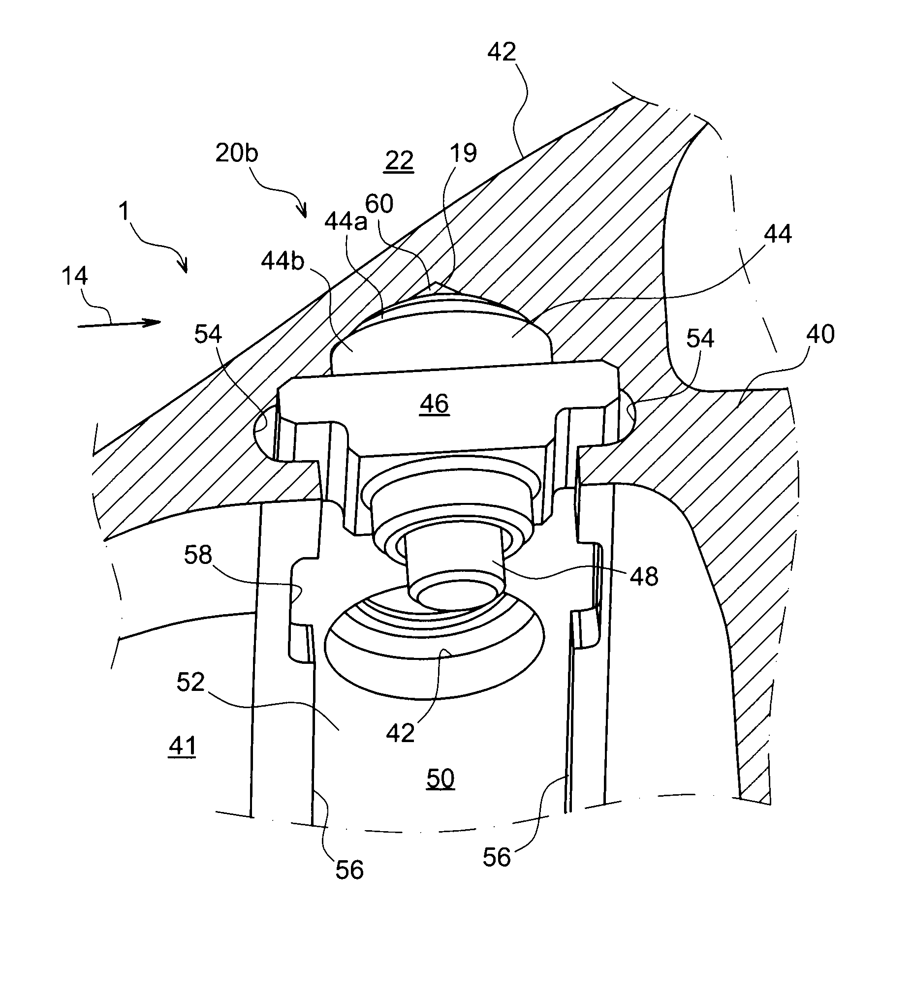
[0040]With reference to FIGS. 3 to 6, a portion of a fan 1 for an aircraft jet turbine engine may be seen, according to a preferred embodiment of the present invention. More specifically, this is the downstream portion 20b of the intake cone, also called a rear cowl shroud, which not only fulfils the function of defining a portion of the outer surface 19 for delimiting the vein 22, but is also intended to bear the balancing system of the jet turbine engine.

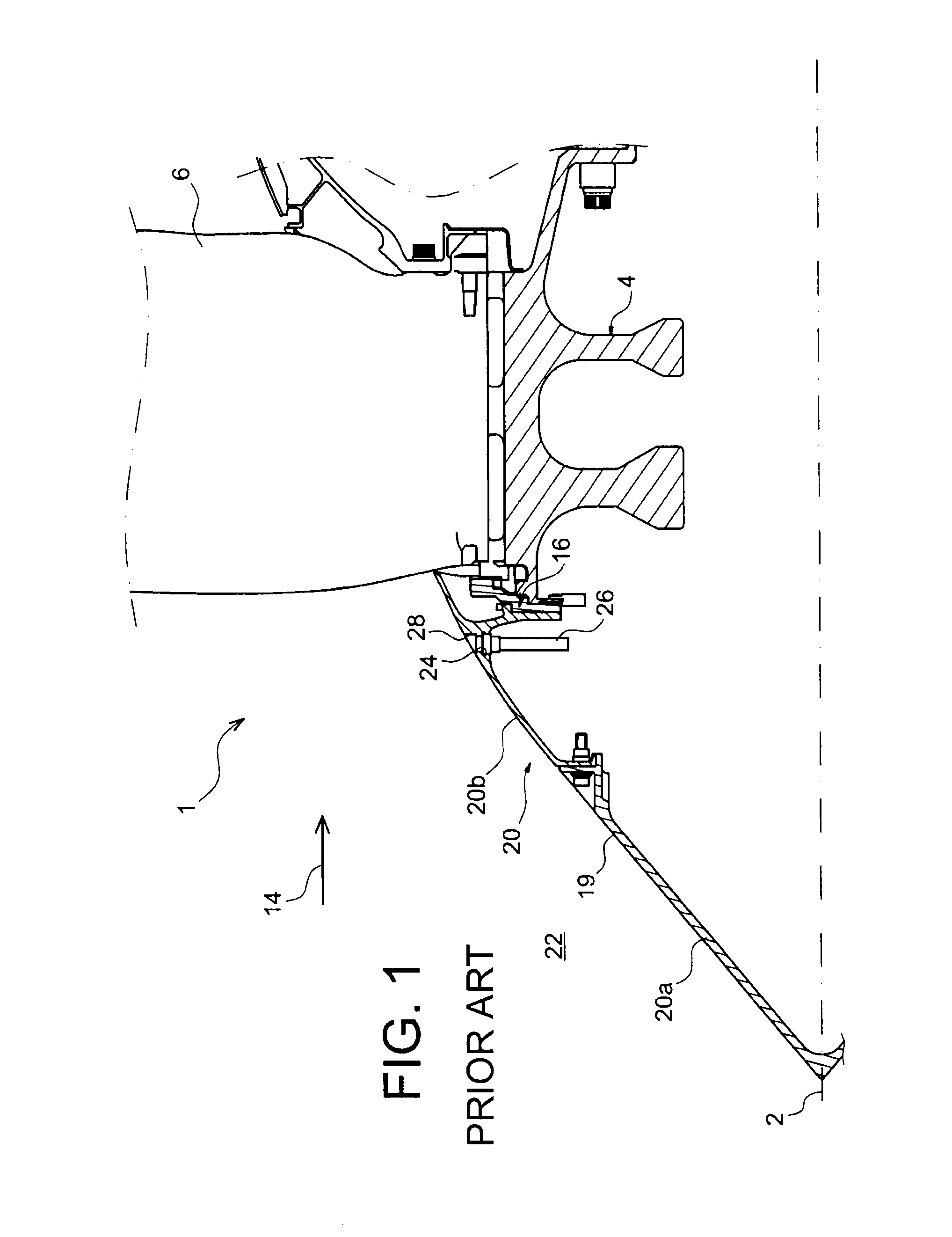
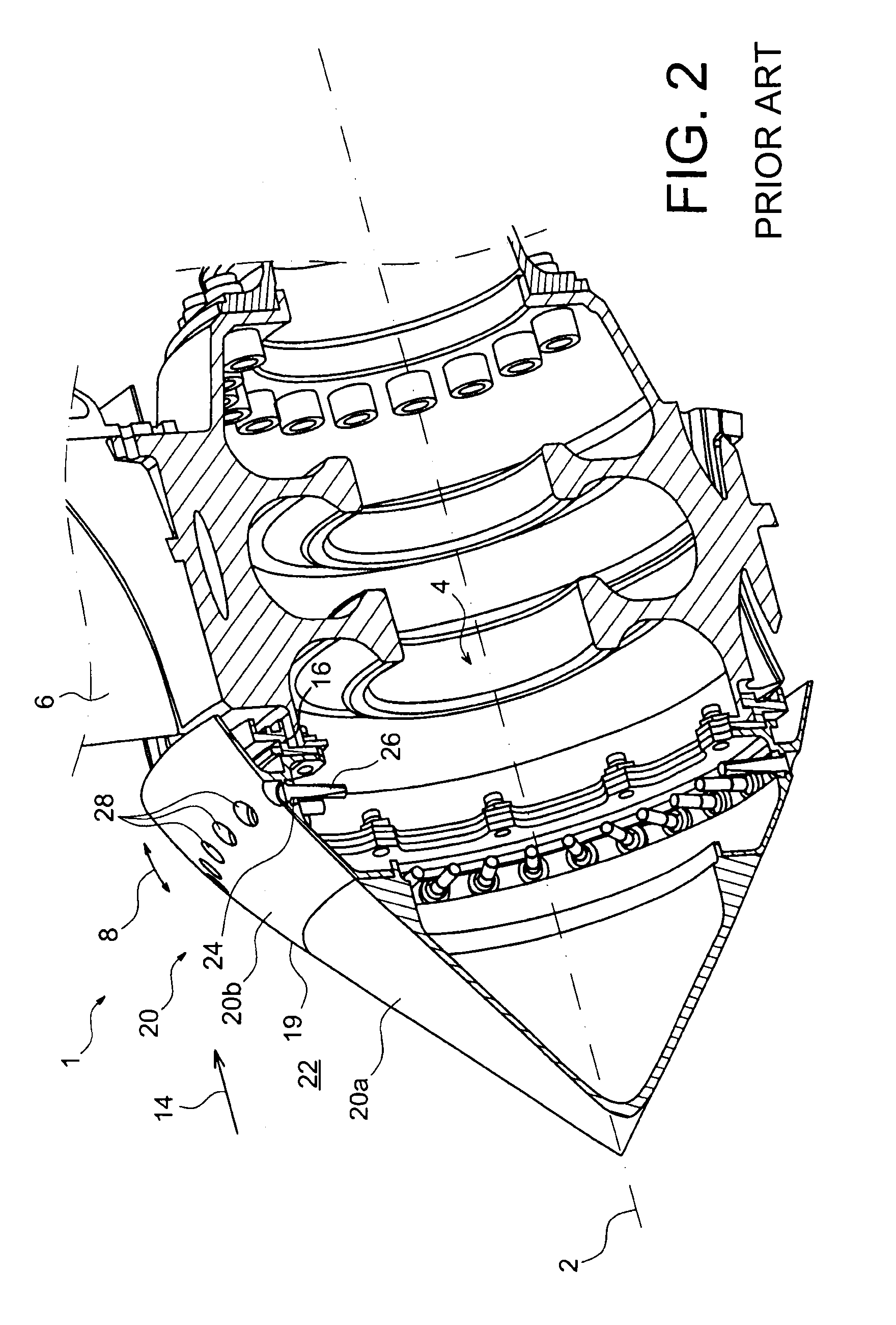
[0041]The other elements of the fan 1 have not been illustrated for some of them or only partly for other ones, but should be considered, for this preferred embodiment, as being identical with or similar to those described with reference to FIGS. 1 and 2 illustrating the prior art. Moreover, in these figures, the elements bearing the same numerical references correspond to identical or similar elements.

[0042]This rear cowl shroud 20b, preferably made in a single piece in aluminium or in one of its alloys, therefore comprises an up...


PUM


Abstract

A fan for an aircraft turbine engine, including an intake cone including a balancing system including a plurality of mass accommodation holes and at least one balancing mass mounted in one of the holes. The balancing system further includes an attachment mechanism exerting pressure that flattens the balancing mass against the bottom of its mass accommodation hole, the accommodation hole being made blind in the intake cone, so as to open out inside the intake cone.

Description

TECHNICAL FIELD[0001]The present invention generally relates to a fan of a turbine engine. More particularly, it relates to the balancing system with which the fan is equipped, allowing final balancing of the turbine engine.[0002]The invention preferably applies to an aircraft jet turbine engine.STATE OF THE PRIOR ART[0003]From the prior art, it is actually known how to equip the fan of a jet turbine engine with an annular balancing flange bearing sensibly positioned masses, in order to achieve final balancing of the jet turbine engine.[0004]With reference to FIGS. 1 and 2, a conventional embodiment known from the prior art is illustrated.[0005]In these figures, a fan 1 with a longitudinal axis or axis of rotation 2, also corresponding to the longitudinal axis of the associated jet turbine engine, may therefore be seen. This fan comprises a fan disk 4 centered on the axis 2, fan blades 6 added onto the disk 4 and spaced apart from each other along a circumferential or tangential dir...

Claims


Application Information

Patent Timeline
Patent Type & Authority Patents(United States)
IPC IPC(8): F01D5/02F04D29/00B64C11/00F02C7/04F04D29/66
CPCF02C7/04F01D5/027F04D29/662Y02T50/671Y02T50/673F05D2200/00Y02T50/60
Inventor BELMONTE, OLIVIERWELLER, LIONEL RENE HENRI
Owner SN DETUDE & DE CONSTR DE MOTEURS DAVIATION S N E C M A
Why Eureka
Try Eureka