Torsional resonance frequency measuring device and method

a frequency measuring device and torsional vibration technology, applied in the direction of liquid/fluent solid measurement, machines/engines, instruments, etc., can solve the problems of torsional vibration along the drive-chain, damage and noise of elements, subject to vibration and noise problems, etc., to increase operation safety and save time and cost.

Active Publication Date: 2015-03-24
IND TECH RES INST
View PDF35 Cites 2 Cited by
  • Summary
  • Abstract
  • Description
  • Claims
  • Application Information

AI Technical Summary

Benefits of technology

[0010]In view of the above potential problems, the present invention provides a torsional resonance frequency measuring device and method applicable to a large-scale power generator or traction motor equipment with a rotating member, such as a large power grid-tied wind turbine, which can use the existing hardware structure of the wind turbine to measure the torsional resonance frequency so as to dispense with on-site measurement by maintenance staff, thereby reducing the cost for parameter adjustment and equipment diagnosis and prognosis, and greatly increasing the maintenance efficiency and operation safety for maintenance staff.
[0013]Therefore, the torsional resonance frequency device and method of the present invention implements real-time remote equipment measurement and diagnosis so as to save time and cost and increase operation safety for maintenance staff.

Problems solved by technology

Since wind turbines in operation must bear wind loads with randomness and turbulence, they are often subject to vibration and noise problems.
When rotational machines are applied to large-scale power generators or traction motor equipments (such as large power grid-tied wind turbines), torsional vibration along the drive-chain is a major factor causing element damage and noise.
However, there are some drawbacks in using such an impact excitation method.
However, since large-scale wind turbines are usually installed at higher places, and most of the wind turbines or wind capturing devices are generally installed on remote mountains, seaside or even offshore islands for achieving preferred wind capture effect and avoiding noise pollution, to make on-site measurement results in high cost and wasting of time.
Further, wind turbines high above the ground pose a potential safety risk to on-site maintenance staff.

Method used


Image

  • Torsional resonance frequency measuring device and method
  • Torsional resonance frequency measuring device and method
  • Torsional resonance frequency measuring device and method

Examples


Embodiment Construction

[0024]The following illustrative embodiments are provided to illustrate the disclosure of the present invention, these and other advantages and effects can be apparent to those in the art after reading this specification.

[0025]To make the present invention more clear, detailed description of conventional electrical connections (such as power sources and voltage signals), coupling methods and basic circuit elements (such as capacitors and diodes) is omitted herein.

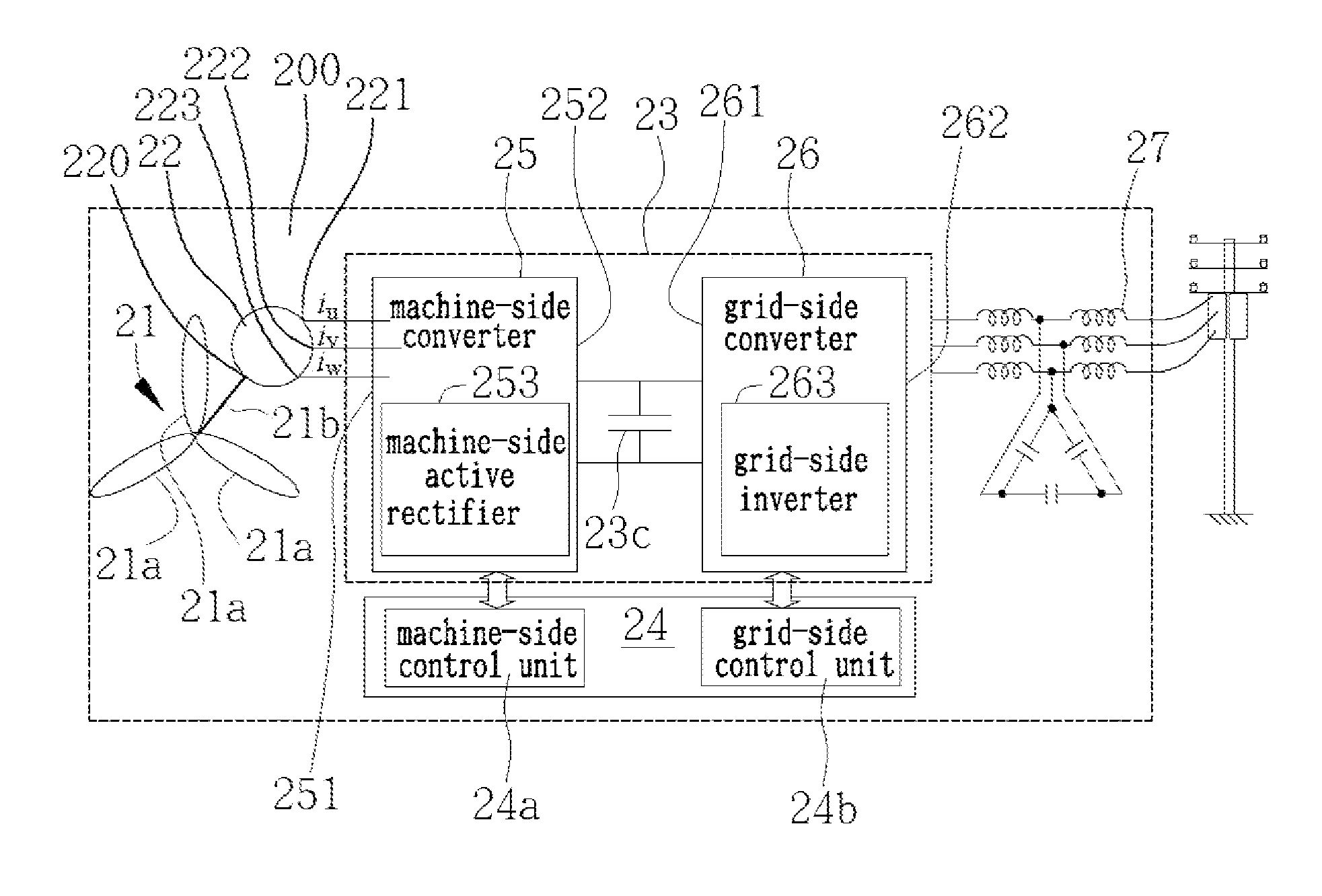
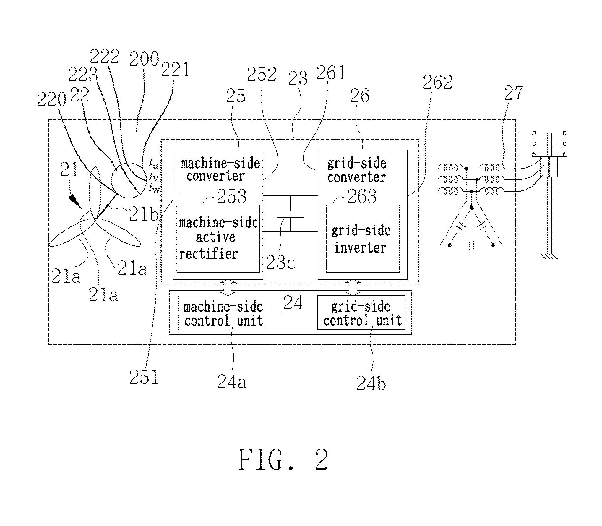
[0026]The present invention provides a torsional resonance frequency measuring device and method applicable to a rotary electric machine such as a large-scale power generator or traction motor equipment such as a large power grid-tied wind turbine. In the following embodiments of the present invention, a grid-tied wind turbine is exemplified as a rotary motor and the embodiments are detailed based on the grid-tied wind turbine.

[0027]Further, same or similar elements in the embodiments are denoted as the same reference numer...


PUM

PropertyMeasurementUnit
torsional resonance frequencyaaaaaaaaaa
torsional resonance frequency measuringaaaaaaaaaa
magnetic fieldaaaaaaaaaa

Abstract

The invention provides a torsional resonance frequency measuring device and method applicable to a large-scale power generating equipment or a traction motor equipment with a rotating shaft, such as a large power grid-tied wind turbine. The invention is characterized by employing a machine-side converter existing in the grid-tied wind turbine to output direct currents to a three-phase PMSG (permanent magnet synchronous generator), such that a pulse torque is generated to mechanically excite a rotor of the three-phase PMSG. Afterwards, a control circuit of the machine-side converter acquires back electromotive force generated by the mechanically excited rotor so as to calculate the torsional resonance frequency of the overall drive-chain system according to the frequency spectrum of the back electromotive force.

Description

TECHNICAL BACKGROUND[0001]1. Technical Field[0002]The present invention relates generally to torsional resonance frequency measuring devices and methods applied to rotating members, and more particularly, to a device and method that measures the torsional resonance frequency of a rotating member supported in an unrestrained free-free drive-chain through impact excitation by using a machine-side converter.[0003]2. Description of Related Art[0004]In recent years, due to the depletion of fossil fuel and environment concerns, a lot of countries have focused on developing wind power generation. In order to generate electric power, the wind turbines have rotating blades driven by the wind, which convert the wind power to the mechanical power, and the mechanical power is then converted into electrical energy by an electrical generator, and finally, the electrical energy is transformed into an appropriate form by a power converter and fed to loads such as road lights, energy storage devices...

Claims


Application Information

Patent Timeline
Patent Type & Authority Patents(United States)
IPC IPC(8): G01L7/00G01H13/00
CPCG01H13/00
Inventor GUEY, ZEN-JEYCHANG, YUN-YUAN
Owner IND TECH RES INST
Why Eureka
Try Eureka