Printing apparatus and operation setting method thereof

a printing apparatus and operation setting technology, applied in the direction of electrical apparatus construction details, digital output to print units, instruments, etc., can solve the problems of poor flexibility in functional enhancement and the like of inkjet printing apparatus, failure of connection, etc., and achieve the effect of flexible functional enhancement and easy implementation of functional enhancement of printing apparatus

Inactive Publication Date: 2015-03-24
CANON KK
View PDF12 Cites 32 Cited by
  • Summary
  • Abstract
  • Description
  • Claims
  • Application Information

AI Technical Summary

Benefits of technology

[0012]For example, a printing apparatus and operation setting method thereof according to this invention are capable of dynamically switching the operation setting in accordance with the setting operation of an add-in card and facilitating flexible functional enhancement.
[0015]The invention is particularly advantageous since the operation setting mode of the controller of a printing apparatus is dynamically switched over in accordance with the type of mounted add-in card, and flexible functional enhancement by an add-in card can be easily achieved.
[0016]Hence, functional enhancement of the printing apparatus can be easily implemented by, for example, inserting a PCI-Express add-in card.

Problems solved by technology

If the add-in card serves as a root-complex, a connection fails.
However, the connection fails when the add-in card serves as an end-point.
Flexibility is poor in functional enhancement and the like of the inkjet printing apparatus.

Method used


Image

  • Printing apparatus and operation setting method thereof
  • Printing apparatus and operation setting method thereof
  • Printing apparatus and operation setting method thereof

Examples


first embodiment

[0099]FIG. 7 is a block diagram showing a schematic control arrangement when an accelerator board for improving performance is mounted on a system board.

[0100]An accelerator board 301 includes an accelerator controller 302. The accelerator controller 302 has the functions of a CPU, a root-complex complying with the PCI-Express specification, a RAM, a ROM, and an encryption unit. The accelerator controller 302 is connected to a system controller 206 via an extension slot 204. In the accelerator controller 302, an MCH (Memory Controller Hub), CPU, RAM, and ROM may be configured as discrete devices. The MCH is a PCI-Express root-complex and is connected to the system controller 206 serving as an end-point via a 4-lane PCI-Express signal line 212. The accelerator controller 302 is higher in CPU performance and memory performance than the system controller 206. The accelerator controller 302 performs interface processing and image processing requiring a high ratio of software control, an...

second embodiment

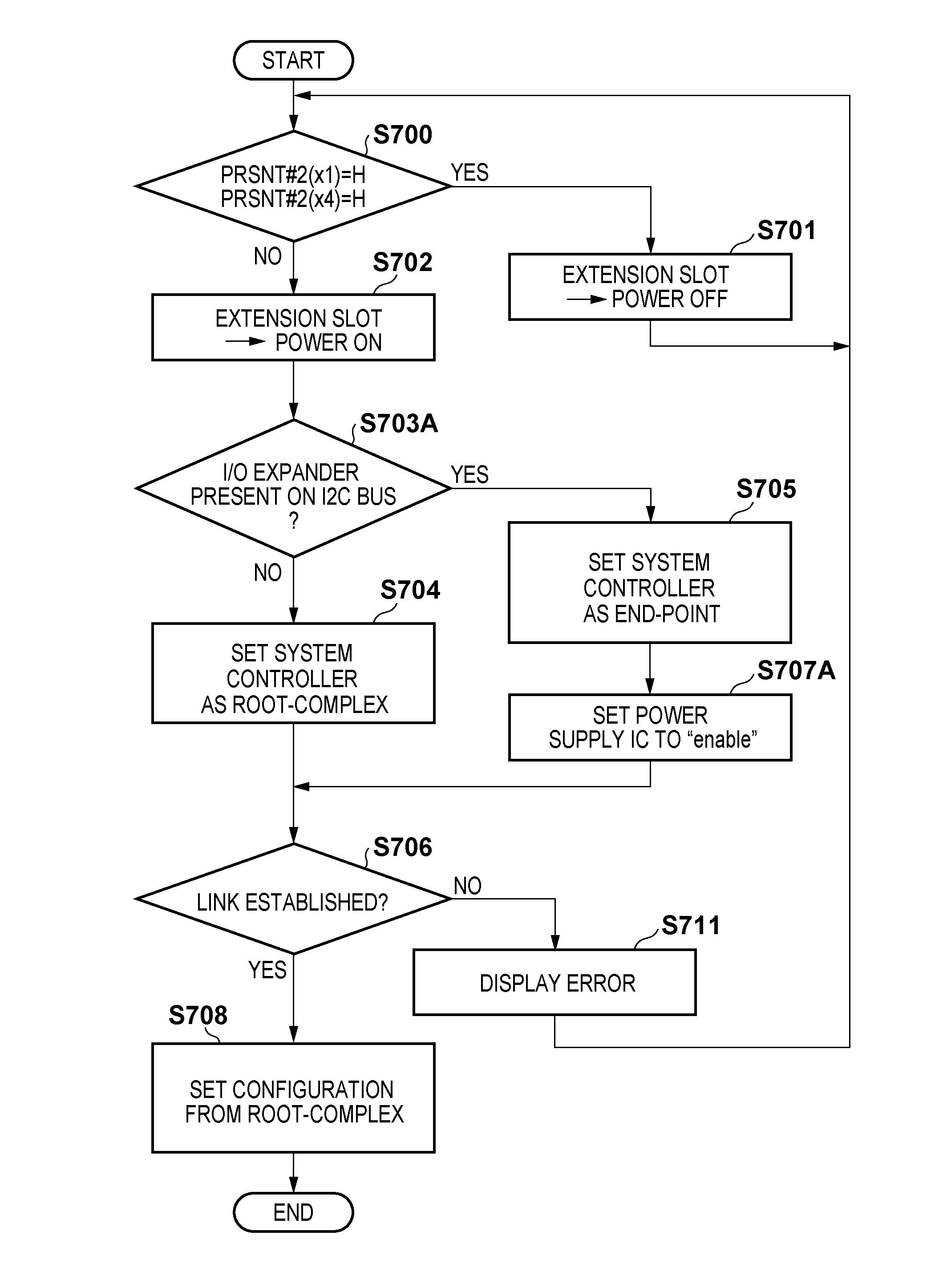
[0125]FIG. 13 is a block diagram showing a schematic arrangement when an accelerator board 301 is mounted on a system board 203 according to the second embodiment.

[0126]A print data processing sequence and the processing contents of print data on the accelerator board 301 are the same as those in the first embodiment, and a description thereof will not be repeated. As for the arrangement of the accelerator board 301, a description of the same arrangement as that in the first embodiment will not be repeated.

[0127]In the second embodiment, an I / O expander 1300 is mounted on the accelerator board 301 and connected to a system controller 206 via an I2C (Inter-Integrated Circuit) bus 1302. The system controller 206 controls a power supply IC 1301 and the like. The I / O expander 1300 is an input / output control circuit with a communication interface.

[0128]The power supply IC 1301 is a DC-DC converter which converts 12 V power supplied from the system board 203 to the accelerator board 301 v...

third embodiment

[0146]FIG. 17 is a block diagram showing a schematic arrangement when an accelerator board 301 is mounted on a system board 203 according to the third embodiment.

[0147]A print data processing sequence and the processing contents of print data on the accelerator board 301 are the same as those in the first and second embodiments, and a description thereof will not be repeated. As for the arrangement of the accelerator board 301, a description of the same arrangement as those in the first and second embodiments will not be repeated.

[0148]In the third embodiment, an I2C bus and power supply line between the accelerator board 301 and the system board 203 are connected via connectors 1702 and 1703. A PCI-Express bus is connected via connectors 1700 and 1701.

[0149]FIG. 18 is a block diagram showing a schematic arrangement when an extension interface (I / F) board 401 is mounted on the system board 203.

[0150]The arrangement of the extension I / F board 401 is the same as that described in the ...


PUM


Abstract

This invention is directed to enhancement of flexibility when connecting an add-in card conforming to the PCI-Express specification. More specifically, the operation mode of the system board of a printing apparatus is configured to cope with both a root-complex and end-point. When an add-in card is inserted into an extension slot, the type of add-in card is discriminated by confirming the ON state of a detection pin. When the inserted add-in card operates as a root-complex, the system board is set to operate as an end-point. When the inserted add-in card operates as an end-point, the system board is set to operate as a root-complex.

Description

BACKGROUND OF THE INVENTION[0001]1. Field of the Invention[0002]The present invention relates to a printing apparatus and operation setting method thereof. Particularly, the present invention relates to a printing apparatus capable of functional enhancement by adding a card or board and an operation setting method thereof.[0003]2. Description of the Related Art[0004]As a high-speed serial interface, a PCI-Express® interface, which is a succeeding specification of the PCI bus system, has been proposed (see, for example, United States Patent Application Publication Nos. 2006 / 0114918, 2006 / 0277344, and 2005 / 0172037). A PCI-Express serial bus has an advantage of reducing the hardware cost because the number of signals is smaller than that in a PCI parallel bus. For example, the number of wires (signal lines) on a board can be reduced, and the substrate area and connector size can be decreased. PCI-Express can simultaneously provide a bandwidth twice or more that of the PCI and thus can ...

Claims


Application Information

Patent Timeline
Patent Type & Authority Patents(United States)
IPC IPC(8): H05K7/10G06F3/12
CPCG06F3/1279G06F3/122G06F3/1221G06F3/1229Y02D10/00
Inventor SAITO, TADAO
Owner CANON KK
Why Eureka
Try Eureka