
Holding units for stay in place molds

a technology of holding units and molds, applied in the field of molds for stay in place, can solve the problems of debilitating the whole structure, difficult alignment and proper connection of individual molds, and external components complicating the construction process, so as to achieve uniform and strong large-scale concrete structures, strong firmness, and excellent resistance to internal pressur

Inactive Publication Date: 2015-04-07
CERAME JOSE JAVIER
View PDF15 Cites 2 Cited by
  • Summary
  • Abstract
  • Description
  • Claims
  • Application Information

AI Technical Summary

Benefits of technology

The invention provides stay in place fiber cement molds that can hold fibers cement with strong firmness without exposing any components at the exterior surface. The molds have excellent resistance to internal pressure created by the liquid cement mixture and can stand without external supports or components. The molds allow for uniform spread of the cement mixture and can be interconnected to produce large concrete structures. Additionally, the molds can incorporate insulating materials without affecting the interior of the constructed wall and provide flat external surfaces. The molds also allow for easy predetermination and distribution of re bars as demanded by a given construction code.

Problems solved by technology

The real challenge in the manufacture and use of said molds is to maintain both fiber cement panels held together firmly and to obtain a highly internal pressure resistance at the internal cavity of the form.
In most instances, said fiber cement panels hare held together by means of vertical and horizontal structural components which, are attached internally or externally to the said panels, debilitating the whole structure.
Said external components complicate the construction process, requiring external supports in order to counteract or balance the internal pressure created once the liquid cement mixture is poured inside the mold.
Similarly, said external components difficult the alignment and proper connection of individual molds, as required in the formation of larger structures.
On the other hand, the use of complicated components assembled through the width of the fiber boards and passing along its internal cavity compromise the firmness and stability of the mold and the strength of the structure constructed with said mold.
In the internal section of the mold, said structures occupy a large area of the internal cavity and thus, represents an obstruction that avoid the uniform contact of the liquid concrete mixture, which results in the formation of a non-monolithic, weak concrete structure.
On the other hand, regarding the external section of the mold, once the concrete structure is made, it is required to eliminate the external section of such components, which means additional work that can negatively affect the interior of the constructed structure.

Method used


Image

  • Holding units for stay in place molds
  • Holding units for stay in place molds
  • Holding units for stay in place molds

Examples


embodiment 9

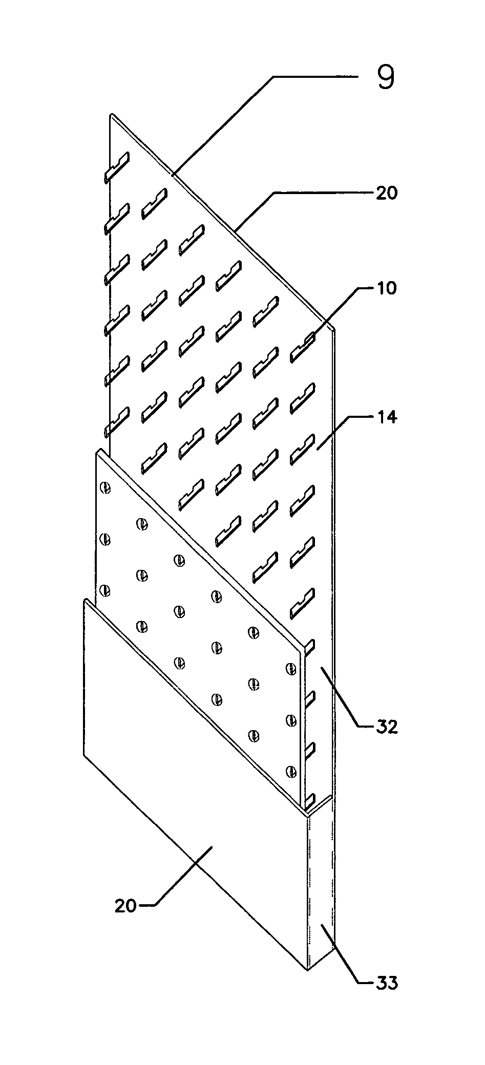
[0027]On the other hand, mold embodiment 9 as illustrated in FIG. 4C has a closing unit 33 enclosing the internal cavity 32 of the mold 9. Said closing unit 33 may be made of fiber cement panel that has been cut off at the convenient size in order to close the internal cavity 32 of the mold 9. Said closing unit 33 may be installed once the mold is already installed at the construction site and previous to fill the internal cavity 32 of the mold 9 with liquid concrete mixture.

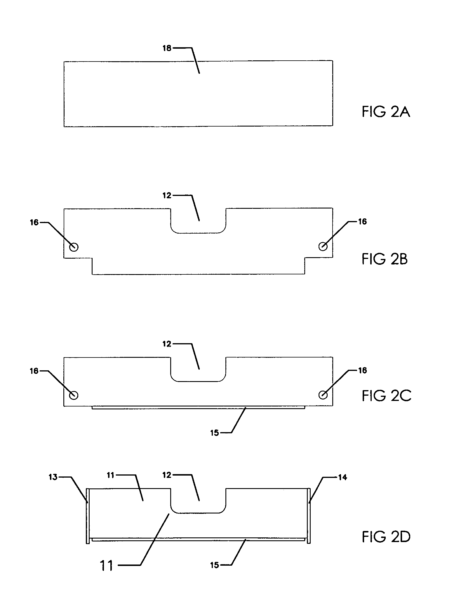
[0028]The manufacture of the mold embodiments illustrated FIGS. 4A to 4C is shown in FIGS. 5A to 5E, wherein the initial step is the proper setting of the fiber cement boards 20. Said setting requires a series of perforations in a particular size or shapes and further distributed in a particular pattern of columns (verticals) and rows (horizontal) at a predetermined distance and within a particular surface area of the fiber cement panels 20. Each perforation is intended to provide a place for fastening a holding...

embodiment 8

[0034]Optionally and depending of the construction needs, interconnecting units 31 may be connected to one of the lateral sides of the mold 7, if necessary, in order to provide a joining mechanism as shown in embodiment 8 illustrated in FIG. 4B, as may be required depending of the size of desired wall under construction.

[0035]In operational terms, the mold embodiments 7, 8 and 9 are used in the construction of concrete or cement walls, houses, buildings and similar structures. FIG. 7 illustrates the assembled of mold embodiment 7 to a given structure site, wherein dowel 52 on construction site 53 is attached to the vertical re-bar 65 and wherein horizontally oriented re-bars 66 are resting on indentations 12 of holding units 10. Similarly, FIG. 8A to 8C illustrate the joining of two mold embodiments 8 in the construction of a larger size wall 68 by means of interconnecting unit 31 and wherein the distribution and accommodation of vertical re-bars 65 and horizontal re-bars 66 inside ...


PUM

PropertyMeasurementUnit
angleaaaaaaaaaa
heightaaaaaaaaaa
lengthaaaaaaaaaa

Abstract

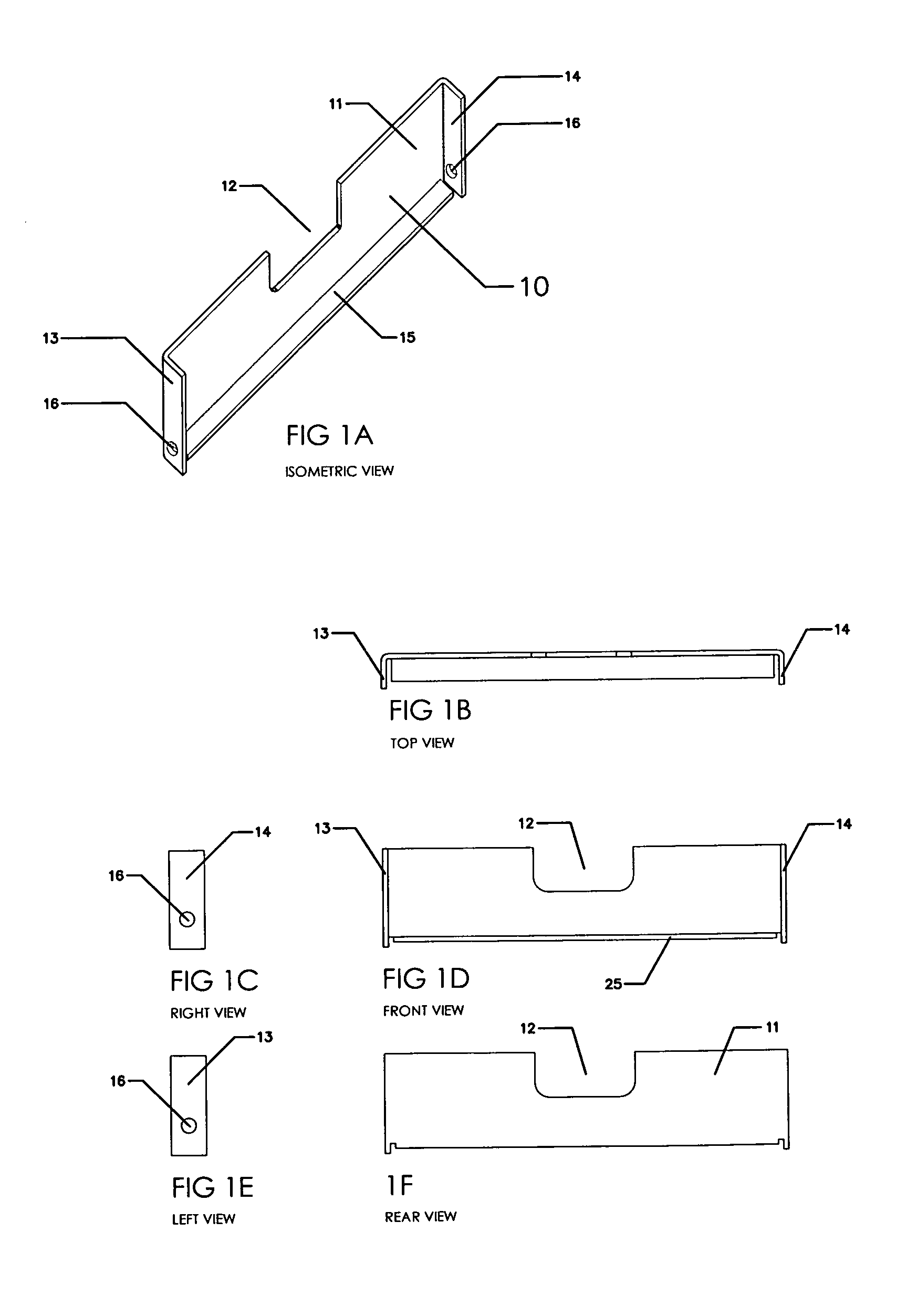
Stay in place molds for the construction of concrete structures having fiber cement panels held together by multiple holding units is described. The holding units requires a flat rectangular main body; an indentation substantially located at the center of the upper side of the flat rectangular main body; left and right lateral edges perpendicularly located at the lateral sides of the rectangular body and a lower edge perpendicularly positioned at the lower side of the bottom side of the flat rectangular main body. They are selectively distributed at the internal cavity of the molds as a series of columns and rows separated from each other at predetermined distance. The particular structure and its distribution pattern facilitate the uniform contact of the liquid cement mixture and increase the strength and resistance of the structure prepared using the molds.

Description

[0001]This application claims priority under 35 USC 120 to U.S. patent application Ser. No. 12 / 633,416 filed on Dec. 8, 2009.TECHNICAL FIELD OF THE INVENTION[0002]This invention relates to stay in place molds for the construction of concrete structures. More particularly, the invention is directed to stay in place construction molds comprising multiple holding units having a particular shape and design that renders monolithic concrete structures of excellent strength.BACKGROUND OF THE INVENTION[0003]Fiber cement panels, also known as fiber cement boards have been used in the elaboration of stay in place molds useful in the construction of concrete structures. In general terms, two fiber cement panels are vertically positioned and held together in order to create an internal cavity intended to be filled with liquid concrete mixture at the construction site.[0004]The real challenge in the manufacture and use of said molds is to maintain both fiber cement panels held together firmly an...

Claims


Application Information

Patent Timeline
Patent Type & Authority Patents(United States)
IPC IPC(8): E04B2/94B28B19/00E04B1/16E04B2/86
CPCB28B19/00E04B1/161E04B2/8635E04B2/8647
Inventor DEL PINO GARCIA, PEDROQUILES PEREZ, PEDRO
Owner CERAME JOSE JAVIER
Learn More