Tunable pulse width laser

a pulse width and laser technology, applied in the direction of laser details, active medium shape and construction, electrical equipment, etc., can solve the problems of insufficient analytical or numerical solutions involving analytical or numerical solutions, inability to comprehensively analyze the theoretical approach and allow determination or optimization of the proper processing parameters, and many of the lasers noted above can be quite expensive and/or larg

Active Publication Date: 2015-04-14
NKT PHOTONICS
View PDF8 Cites 1 Cited by
  • Summary
  • Abstract
  • Description
  • Claims
  • Application Information

AI Technical Summary

Benefits of technology

[0008]In one aspect, the disclosure provides a method of operating a pulsed laser system so as to allow the time duration of output optical pulses from the laser system to be tuned, comprising: providing a laser system that provides an optical output pulse having a selected temporal pulse width at least in part due to the providing of spectral dispersion that introduces a change in temporal pulse width responsive to the spectral bandwidth modification of seed pulses; and providing a second output pulse having a desired temporal pulse width that is different than the selected temporal pulse width from the laser system by changing at least one of the amount of spectral bandwidth modification or the amount of spectral dispersion so as to provide a different amount of pulse width change than that used to generate the pulses having the selected temporal pulse width.
[0016]In one practice, the method can comprise changing both of the amount of spectral bandwidth modification and the amount of spectral dispersion so as to provide substantially continuous tuning of the temporal pulse width of output pulses of the laser system over a selected range of temporal pulse widths and so as to limit the amount of distortion of output pulses having temporal pulse widths within the selected range.
[0017]Typically the output pulses from the laser system will have longer time durations than the seed pulses, and in various practices of the disclosure the output pulses can demonstrate a percentage change in the pulse duration tunability that can range to as much as 100%, 200%, 300%, 500% or even 1000%. That is, the laser can provide one output pulse having a time duration that is 500%, for example, of the time duration of another output pulse. The laser system, in some practices, can provide substantially continuous tuning of the time duration of the output pulses over one or more of the foregoing ranges. Percentage variation can be determined by subtracting the shorter pulse width from the longer and dividing by the shorter.
[0020]In a further aspect, the disclosure provides a method of producing an output pulse from a laser system, comprising: providing a pulsed laser (e.g., a mode locked pulsed fiber laser, such as passively mode lock fiber laser based on a SESAM mode locking element) providing pulses having a spectral bandwidth and a selected time duration (e.g., the selected time duration being no less than 1 ps and no greater than 100 ps); changing the spectral bandwidth of the optical pulses downstream of the pulsed laser by causing the pulses to undergo self phase modulation; spectrally dispersing the optical pulses having the changed spectral bandwidth so as to change the time duration thereof by an amount that is responsive to the change in spectral bandwidth; and providing output pulses having a time duration that is different from the selected time duration responsive to the changing of the spectral bandwidth and spectral dispersion. Providing the output pulses can include refraining from any compressing of the output pulses that would cause their time duration to be less than a selected percentage, such as, for example 75%, 50%, or 25% of the time duration of the output pulses prior to compression.
[0029]The laser system can refrain from any compressing of the output pulses that would cause their time duration to be less than a selected percentage, such as, for example 75%, 50%, or 25% of the time duration of the output pulses prior to compression.
[0030]Typically the laser system is configured such that one or both of the amount of spectral bandwidth change or the amount of spectral dispersion can be selectively changed for selectively changing the time duration of the pulses downstream of the spectrally dispersive optical element, thereby providing a tunable pulse width laser system. The laser system can comprise a controller. For example, the laser system can comprise a controller for controlling the gain of the amplifier, thereby controlling the amount of self phase modulation and the amount of spectral bandwidth modification. Where the nonlinear optical waveguiding element comprises a passive optical waveguide, the laser system can comprise a variable optical attenuator for changing the self phase modulation introduced by the passive optical waveguide, and the controller can control the variable optical attenuator for controlling the attenuation and hence the amount of spectral bandwidth modification. The controller can thus control the time duration of output pulses.

Problems solved by technology

Unfortunately, establishing a useful laser processing window for processing a particular material can be a largely empirical process involving a fair amount of trial and error and variation of many of the above laser processing parameters.
There is typically no comprehensive theoretical approach involving analytical or numerical solutions that allow determination or optimization of the proper processing parameters for processing a particular material.
Unfortunately, such variation, if properly empirically explored, can require the use of many different types of lasers, as one laser type is often quite limited in the range of processing parameters that can be varied.
As a further impediment to a full or efficient exploration of a processing window for the laser processing of a material, many of the lasers noted above can be quite expensive and / or large.

Method used


Image

  • Tunable pulse width laser
  • Tunable pulse width laser
  • Tunable pulse width laser

Examples


Embodiment Construction

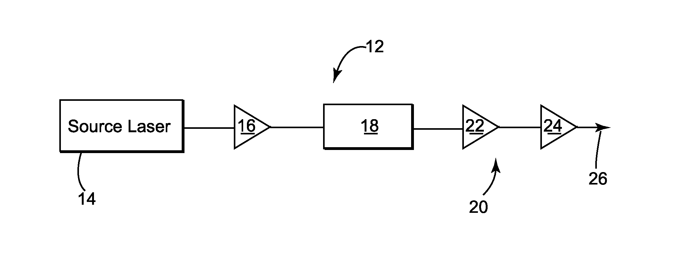
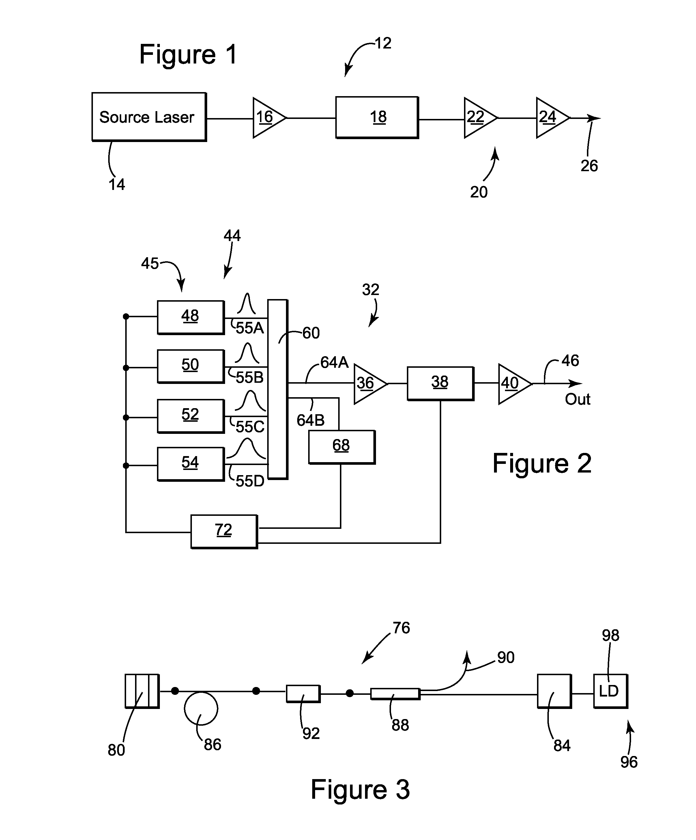
[0069]FIG. 1 schematically illustrates one embodiment of a tunable temporal pulse width laser 12 according to the present disclosure. The tunable temporal pulse width laser 12 can include a tunable source laser 14, a preamplifier 16, a modulator 18, which can be configured as a pulse picker, and cascade of amplifiers 20, which cascade 20 can include the amplifiers 22 and 24. Typically the amplifier 24 is the most downstream amplifier of the tunable temporal pulse width laser 12 and is configured as a power amplifier. The tunable temporal pulse width laser 12 can comprise an output, indicated schematically on FIG. 1 by arrow 26, for outputting the pulses. In various practices of the disclosure, the tunable source laser 14 and / or the tunable temporal pulse width laser 12 can produce fast, ultrafast or ultrashort pulses, wherein the time duration of the pulses from the source laser (and hence of the output pulses 26 of the laser 12) can be changed, such as by being changed responsive t...


PUM


Abstract

A method of tuning the time duration of laser output pulses, the method including spectrally dispersing optical pulses and further comprising providing an optical pulse having a time duration and a spectral bandwidth; spectrally dispersing (243, 245) the optical pulse so as to provide a selected change in the time duration of the pulse responsive to the spectral bandwidth of the pulse; outputting (226) an optical output pulse having a first time duration that is responsive to the selected change in time duration; providing another optical pulse; changing the amount of spectral bandwidth of the another optical pulse (272) to be different than that of the optical pulse or changing the amount of spectral dispersion so that spectrally dispersing the another optical pulse provides a change in time duration that is different than the selected change; and outputting (226) another optical output pulse having a second time duration that is responsive to the different change in time duration, the second time duration of the another optical output pulse being different than the first time duration of the optical output pulse.

Description

[0001]The present application claims priority to U.S. Provisional Patent Application No. 61 / 345,145, filed May 16, 2010 to inventors Clowes et al. and entitled “Tunable Pulsewidth Laser”, and which is incorporated herein by reference in its entirety.TECHNICAL FIELD[0002]The present disclosure relates to tunable lasers, such as, for example, fiber lasers having a tunable pulse width, and to the making and using of such lasers.BACKGROUND OF THE DISCLOSURE[0003]Recent years have seen considerable progress made in the art of laser processing of materials. Lasers can avoid some of the disadvantages of more conventional machining techniques, such as drilling a hole using a drill bit or shaping a material with a rotating end mill. For example, a laser machining process typically does not rely on a rotating machine tool that can wear out due to continued mechanical contact with the work material. There are a myriad of other advantages known to those of ordinary skill in the art regarding ad...

Claims


Application Information

Patent Timeline
Patent Type & Authority Patents(United States)
IPC IPC(8): H01S3/10H01S3/13H01S3/00H01S3/067H01S3/094H01S3/0941H01S3/11H01S3/16H01S3/23
CPCH01S3/11H01S3/06754H01S3/1112H01S3/0057H01S3/094003H01S3/0941H01S3/1618H01S3/2383H01S2301/08H01S3/0085
Inventor ALMEIDA, PAULOCLOWES, JOHN REDVERSDUPRIEZ, PASCALGRUDININ, ANATOLY BORISOVICH
Owner NKT PHOTONICS
Why Eureka
Try Eureka