Floating-point adder

a floating point adder and adder technology, applied in the field of data processing systems, can solve the problems of loss of precision, disadvantageous degree of latency in the processing path, and reduce the maximum operating clock frequency that may be used, and achieve the effect of reducing latency and reducing latency

Active Publication Date: 2015-04-14
ARM LTD
View PDF9 Cites 14 Cited by
  • Summary
  • Abstract
  • Description
  • Claims
  • Application Information

AI Technical Summary

Benefits of technology

[0013]The present technique recognises that instead of explicitly computing a sticky bit by a logical OR of the bits shifted out of the significance range, it is possible to indirectly calculate a bit with the same value by determining the carry out from a sum dependent upon a count of trailing zeros within the shifted out bits and the difference in the exponent values, with one of these addends first being subject to a NOT operation. The calculation of the trailing zeros count can be performed in parallel with the right shift performed upon the smaller addend thereby advantageously reducing latency (delay) through the adder circuit.
[0021]It will be appreciated that the floating point addition mechanisms described above require an identification of which input addend has the greater size (at least in terms of having the largest exponent value or the equal largest exponent value or the equal largest exponent value). One way of achieving this is to compare the exponent values before the addition is commenced and then to switch the input addends to the appropriate paths matching the path for the larger addend and the path for the smaller addend. This approach adds relatively little gate count, but increases latency of the operation.
[0028]The minimum value circuitry may be configured to generate one or more high order bits of the result shift value before one or more low order bits of the result shift value are generated. This is advantageous as it permits a result shifting circuitry in the form of a logarithmic shifter to commence its right shift of the intermediate mantissa to produce the result mantissa prior to the full precision of the result shift value being available. This reduces the latency of the near-path.
[0044]It will be appreciated that the technique of reducing latency within the near-path may be used independently of the technique for reducing latency within the far-path. However, the combined use of these techniques is advantageous in that the near-path and the far-path may be maintained in balance with respect to their latency.

Problems solved by technology

Such an alignment will shift the least significant bits of the mantissa value out of the significance range of the mantissa result and accordingly there will be a loss of precision.
A problem with this approach is that the OR operation may be many bits wide and introduce a disadvantageous degree of latency in the processing path.
Increases in latency can reduce the maximum operating clock frequency that may be used, reduce timing slack and have other negative consequences.

Method used


Image

  • Floating-point adder
  • Floating-point adder
  • Floating-point adder

Examples


Embodiment Construction

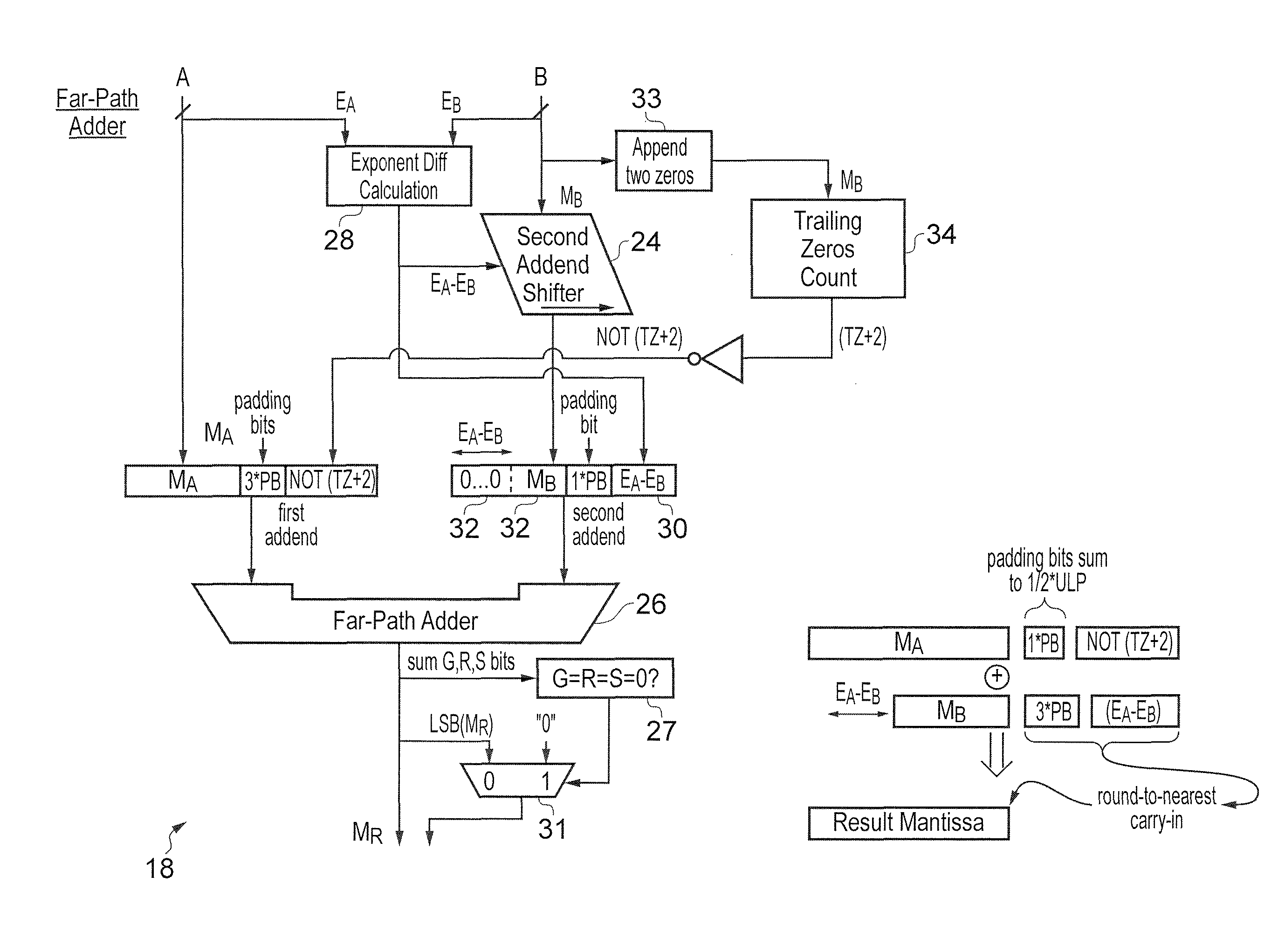
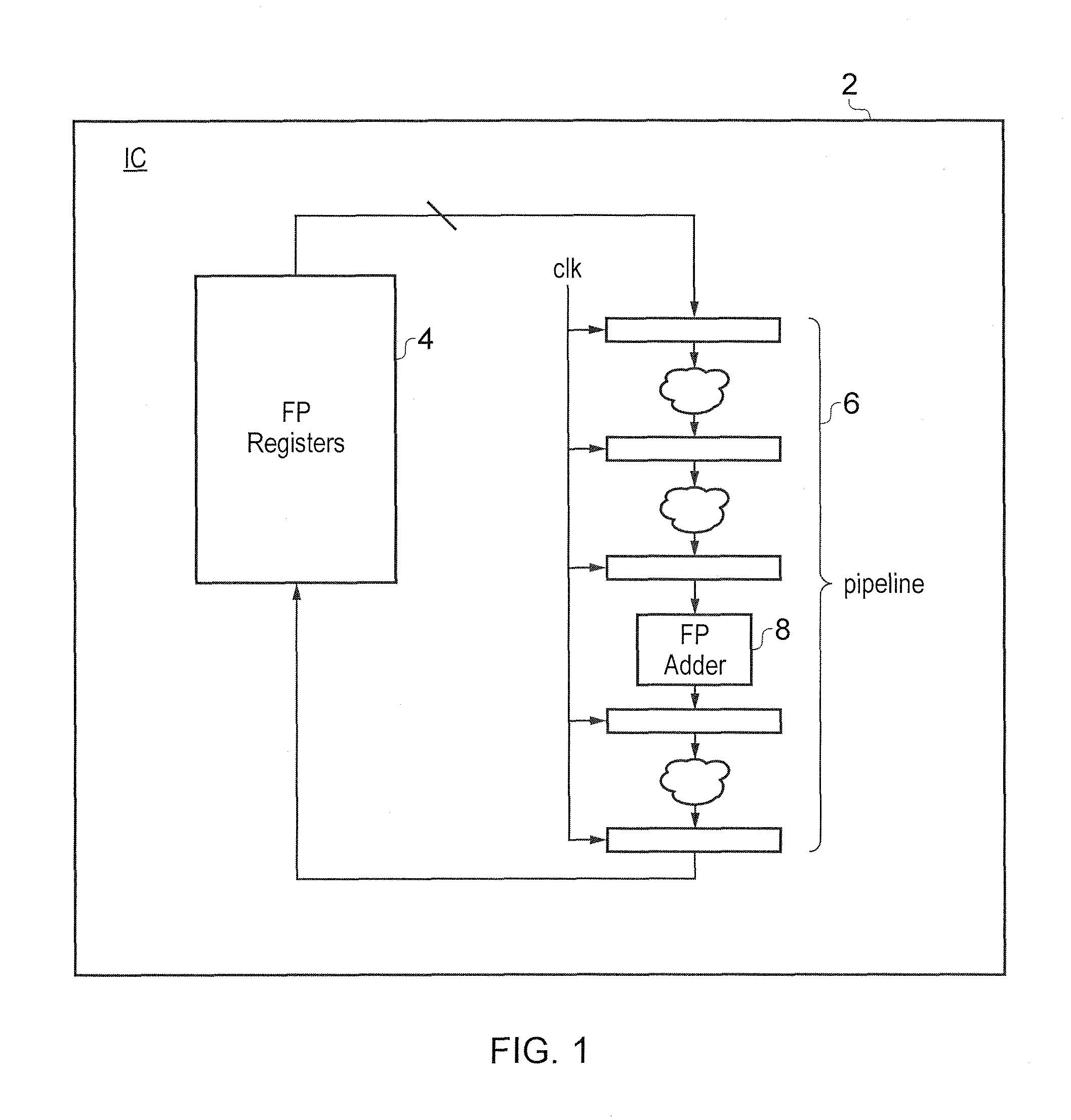
[0059]FIG. 1 schematically illustrates an integrated circuit 2 including a bank of floating point registers 4 for storing floating point numbers and a data processing pipeline 6 including a plurality of processing stages with at least one of the processing stages providing floating point adder circuitry 8. In accordance with conventional pipelining within data processing systems, the pipeline stages are driven by a common clock signal which controls the advancement of the result(s) of one processing stage to the next processing stage. Measures which can reduce the latency associated with the processing being performed at each processing stage are advantageous as they, for example, may permit a higher clock frequency to be used and accordingly achieve a higher amount of data processing within a given amount of time. Reduced latency may also increase the timing slack between processing stages which has the advantage of making the design more robust.

[0060]In floating point adder circui...


PUM


Abstract

Floating point adder circuitry 16, 18, 20 is provided with far-path circuitry 18 and near-path circuitry 20. The far-path circuitry utilises a count of trailing zeros TZ and a difference in the input operand exponents to form respective suffix values which are concatenated with the mantissas of the input addends and serve when summed to generate a carry out taking the place of a conventionally calculated sticky bit. Within the near-path, minimum value circuitry 46 is used to calculate the lower of a leading zeros count of the intermediate mantissa produced in a subtraction and the larger of the input operand exponent values such that a left shift applied to the intermediate mantissa value is not able to produce a invalid floating point result due to applying a left shift to remove leading zeros that is too larger and accordingly corresponds to an exponent which cannot be validly represented.

Description

[0001]This application claims priority to GB Application No. 1111035.0 filed Jun. 29, 2011 and GB Application No. 1111399.0 filed Jul. 5, 2011, the entire contents of each of which are incorporated herein by reference.BACKGROUND OF THE INVENTION[0002]1. Field of the Invention[0003]This invention relates to the field of data processing systems. More particularly, this invention relates to the field of floating point adders.[0004]2. Description of the Prior Art[0005]It is known within data processing systems to provide floating point adders which can add and subtract floating point numbers. Such floating point numbers may comprise a sign bit, an exponent field and a mantissa field. An example of the format of floating point numbers and operations of floating point arithmetic may be found within the IEEE 754 Standard.[0006]When adding (or subtracting, which may be achieved by adding with one of the inputs first modified), it is normal that the addend with the smaller exponent will be r...

Claims


Application Information

Patent Timeline
Patent Type & Authority Patents(United States)
IPC IPC(8): G06F7/42G06F7/485G06F7/499
CPCG06F7/485G06F7/49942G06F7/49952
Inventor NYSTAD, JORN
Owner ARM LTD
Why Eureka
Try Eureka