Surface topographies for non-toxic bioadhesion control

a bioadhesion control and surface topography technology, applied in the field of non-toxic bioadhesion control surface topographies, can solve the problems of increasing the hydrodynamic drag of the u.s. navy, increasing the range, speed and maneuverability of naval vessels, and increasing fuel consumption by up to 30-40%

Active Publication Date: 2015-04-28
UNIV OF FLORIDA RES FOUNDATION INC
View PDF78 Cites 82 Cited by
  • Summary
  • Abstract
  • Description
  • Claims
  • Application Information

AI Technical Summary

Problems solved by technology

Biofouling is estimated to cost the U.S. Navy alone over $1 billion per year by increasing the hydrodynamic drag of naval vessels.
This in turn decreases the range, speed, and maneuverability of naval vessels and increases the fuel consumption by up to 30-40%.
Thus, biofouling weakens the national defense.
Moreover, biofouling is also a major economical burden on commercial shipping, recreational craft, as well as civil structures, bridges, and power generating facilities.
Any substrate in regular contact with water is likely to become fouled.
No surface has been found that is completely resistant to fouling.
Due to the vast variety of marine organisms that form biofilms, the development of a single surface coating with fixed surface properties for the prevention biofilm formation for all relevant marine organisms is a difficult if not impossible task.
Use of these types of coatings has caused damage to the marine ecosystem, especially in shallow bays and harbors, where the biocides can accumulate.
The silicone-based coating requires several layers to make it effective, and therefore it can be quite costly.
However, they are subject to abrasion, and therefore their use is limited to areas that are not susceptible to damage caused by ice or debris.
Biofouling is similarly a problem for surfaces used in biomedical applications.
The accumulations of bacteria, i.e. a biofilm, on implanted devices such as orthopedic prostheses present a significant risk of infection leading to complications as severe as death.
In cosmetic implants, devices such as breast implants are fouled with fibroblasts and acellular extracellular matrix resulting in a hard fibrous capsule and subsequent implant rupture.
Blood contacting surfaces such as artificial heart valves and artificial vascular grafts are fouled by proteins such as fibrinogen that initiate the coagulation cascade leading in part to heart attack and stroke.
The accumulated affect of bio fouling on chronic and acute disease states, its contribution to morbidity and its massive medical expenses places biofouling as one of the major issues facing modern medicine.

Method used


Image

  • Surface topographies for non-toxic bioadhesion control
  • Surface topographies for non-toxic bioadhesion control
  • Surface topographies for non-toxic bioadhesion control

Examples


examples

[0204]It should be understood that the Examples described below are provided for illustrative purposes only and do not in any way define the scope of the invention.

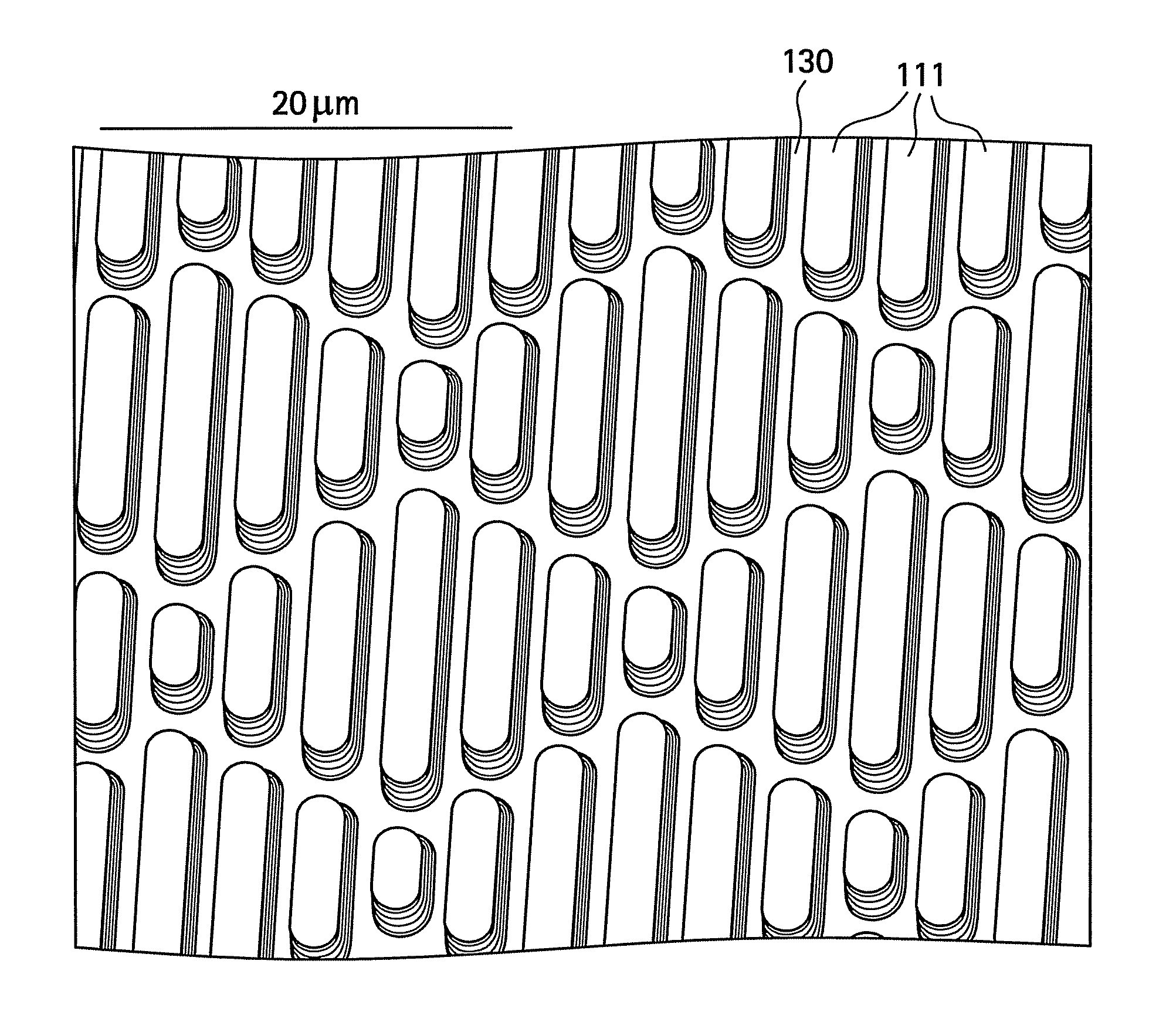
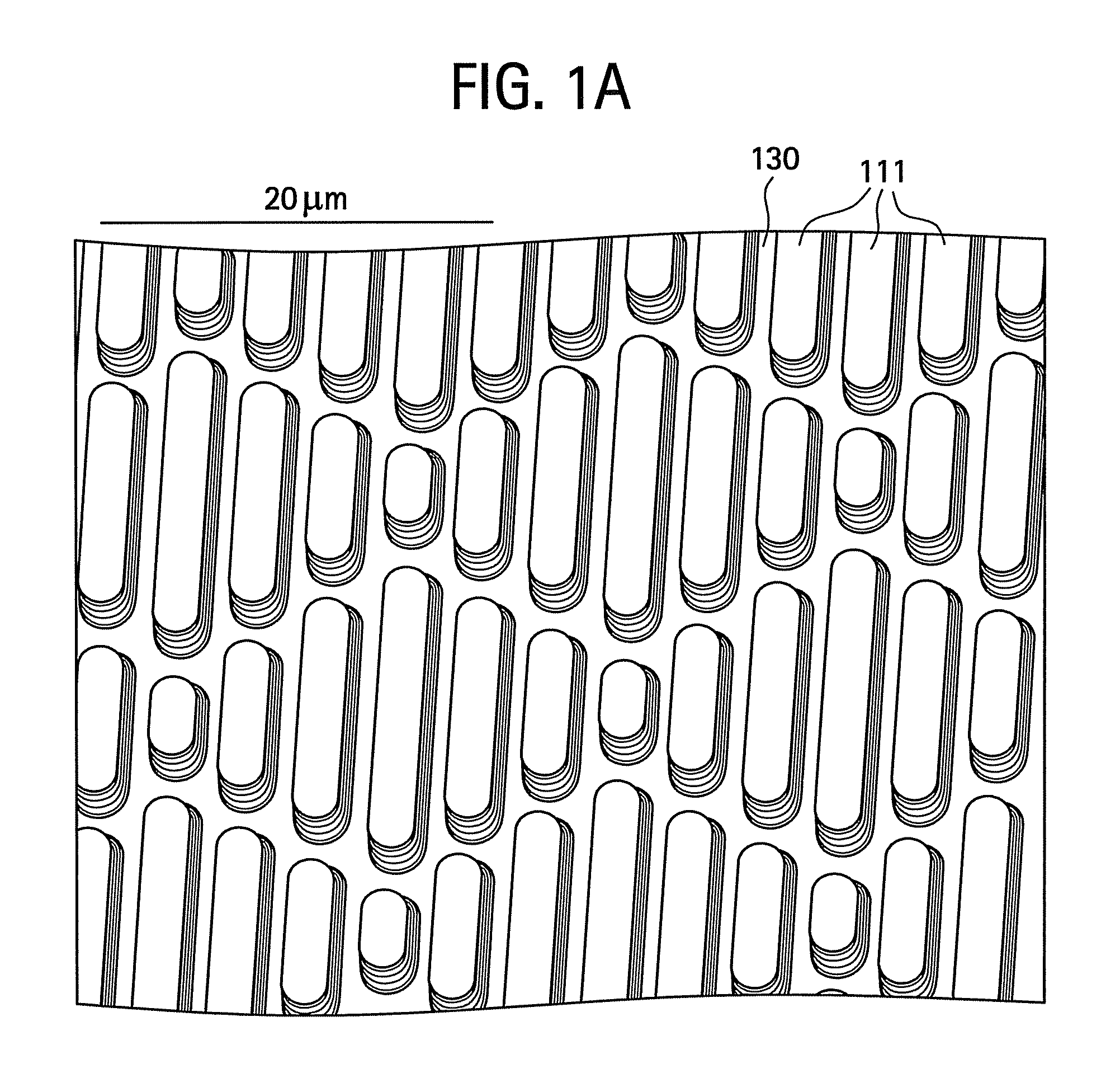
[0205]An experiment was performed to compare the performance of an exemplary surface architecture according to the invention having features formed from a PDMS elastomer as compared to a planar uncoated control surface (the same PDMS elastomer) against bioadhesion of algae spores. The inventive surface topography was the Sharklet shown in FIG. 1(a). Following 45 minutes of exposure, as shown in FIG. 8(a), the settlement density of algae spores on the smooth control sample was about 720 / mm2, while the settlement density for the surface architecture according to the invention was only about 100 / mm2, or only about 15% of the settlement density of the control. FIG. 8(b) is a scanned light micrograph image of the surface of the control, while FIG. 8(c) is a scanned light micrograph image of the surface of the surface architect...


PUM

PropertyMeasurementUnit
average distanceaaaaaaaaaa
thicknessesaaaaaaaaaa

Abstract

Disclosed herein is an article that includes a first plurality of spaced features. The spaced features are arranged in a plurality of groupings; the groupings of features include repeat units; the spaced features within a grouping are spaced apart at an average distance of about 1 nanometer to about 500 micrometers; each feature having a surface that is substantially parallel to a surface on a neighboring feature; each feature being separated from its neighboring feature; the groupings of features being arranged with respect to one another so as to define a tortuous pathway. The plurality of spaced features provide the article with an engineered roughness index of about 5 to about 20.

Description

CROSS-REFERENCE TO RELATED APPLICATIONS[0001]This application is a continuation-in-part (CIP) application of U.S. patent application Ser. No. 11 / 567,103, now U.S. Pat. No. 7,650,848, which is a continuation-in-part (CIP) application of U.S. patent application Ser. No. 11 / 202,532 entitled “SURFACE TOPOGRAPHY FOR NON-TOXIC BIOADHESION CONTROL” which was filed on Aug. 12, 2005, now U.S. Pat. No. 7,143,709, which is a CIP of U.S. patent application Ser. No. 10 / 780,424 entitled “DYNAMICALLY MODIFIABLE POLYMER COATINGS AND DEVICES” which was filed on Feb. 17, 2004, now U.S. Pat. No. 7,117,807, each of which are incorporated by reference in their entirety into the present application.STATEMENT REGARDING FEDERALLY SPONSORED RESEARCH OR DEVELOPMENT[0002]The United States Government has rights in this invention pursuant to Office of Naval Research (ONR) Grant No. N00014-02-1-0325FIELD OF THE INVENTION[0003]The invention relates to articles and related devices and systems having surface topogr...

Claims


Application Information

Patent Timeline
Patent Type & Authority Patents(United States)
IPC IPC(8): B63B59/04B08B17/02A61L27/00A61F2/02B08B17/06A41D31/00A61F2/00A61F2/12A61F2/24A61L2/02B63B1/36B64D15/00
CPCB08B17/06A41D31/0077A61L2/02B08B17/065B63B59/04B64D15/00Y02T70/123A61F2002/009A61F2002/0086A61F2/0077A61F2/12A61F2/24B63B1/36F05C2253/12Y02T70/121A61M25/00A61M25/0017A61M2025/006Y10T428/24355Y10T428/24372A41D31/305Y02T70/10
Inventor BRENNAN, ANTHONY B.LONG, CHRISTOPHER JAMESBAGAN, JOSEPH W.SCHUMACHER, JAMES FREDERICKSPIECKER, MARK M.
Owner UNIV OF FLORIDA RES FOUNDATION INC
Why Eureka
Try Eureka