Top-firing hot blast stove

a stove and top-firing technology, applied in the direction of combustion types, furnaces, lighting and heating apparatuses, etc., can solve the problems of inability to form, disadvantageous limitation of the life of the stove, and damage to the repeating cooling and heating, so as to improve the combustion efficiency of the burner system, improve the hot-blast generating capability, and reduce the temperature difference

Inactive Publication Date: 2015-04-28
NIPPON STEEL & SUMIKIN ENG CO LTD +1
View PDF31 Cites 4 Cited by
  • Summary
  • Abstract
  • Description
  • Claims
  • Application Information

AI Technical Summary

Benefits of technology

[0034]According to the top-firing hot blast stove of the present invention, as is clear from the above description, a swirling flow of mixed gas and a linear flow of fuel gas or combustion air are generated inside the burner duct, and these flows are combusted inside the burner duct, so that combustion gas with a linear component and a swirling component are generated. As a result, it becomes possible to form the mixed gas including sufficiently mixed fuel gas and combustion air inside the burner system, and to thereby enhance the combustion efficiency in burner system. Moreover, it becomes possible to introduce the combustion gas with sufficient linear component into the combustion chamber from the burner duct, so that a large swirling flow of combustion gas can be formed inside the combustion chamber and can be supplied to the entire checker chamber, which makes it possible to provide the top-firing hot blast stove excellent in hot-blast generating capability. Further, the swirling component of the combustion gas in the burner duct forms a negative pressure region, and high temperature atmosphere in the combustion chamber is taken in the negative pressure region so that radiant heat thereof is supplied to the inner wall of the burner duct. As a result, it becomes possible to decrease temperature difference on the inner wall of the burner duct between in combustion operation and in air blasting operation, and to cancel or reduce a repeated cycle of cooling and heating therein, so that the durability of the refractory material placed on the inner wall can be enhanced.

Problems solved by technology

More specifically, the burner duct is alternately subjected to cooling in combustion operation and heating in air blasting operation in a repeated manner, and thus repeated cooling and heating tends to damage, for example, a refractory material (ceramics such as bricks) which protects an inner wall of the burner duct, whereby the life thereof is disadvantageously limited.
Therefore, if a large swirling flow of mixed gas as shown in FIG. 9, and by extension a swirling flow of combustion gas resulting from combustion of the swirling flow, are simply formed in the burner duct BD in an attempt of achieving sufficient mixing of combustion air with fuel gas to form mixed gas, it is not possible to form, inside the combustion chamber N, a large swirling flow (X4-direction flow) capable of supplying high-temperature combustion gas to the entire region of the checker chamber T because the combustion gas does not have a sufficient linear component.

Method used


Image

  • Top-firing hot blast stove
  • Top-firing hot blast stove
  • Top-firing hot blast stove

Examples


Embodiment Construction

[0044]Hereinafter, a description will be given of embodiments of a top-firing hot blast stove of the present invention with reference to the drawings.

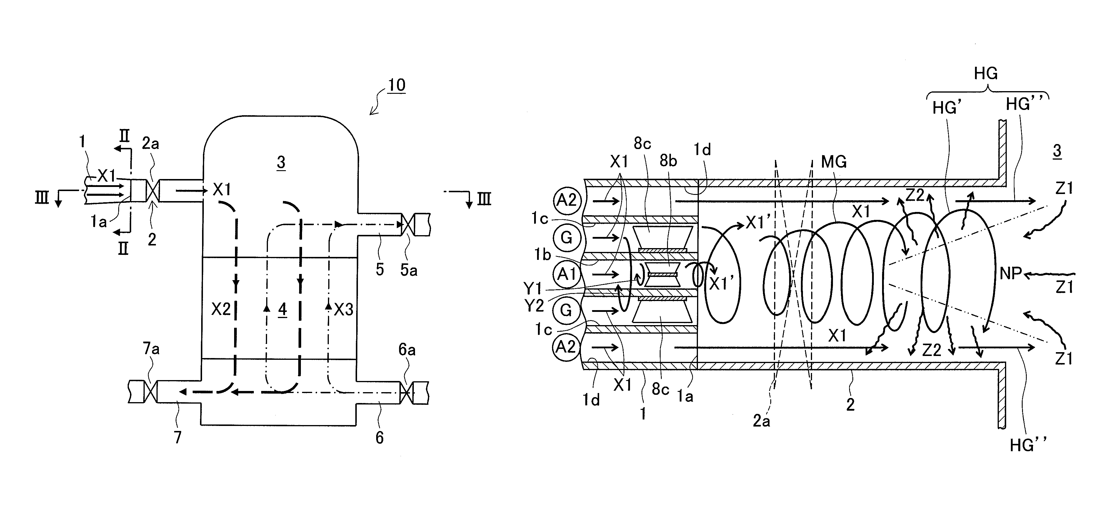
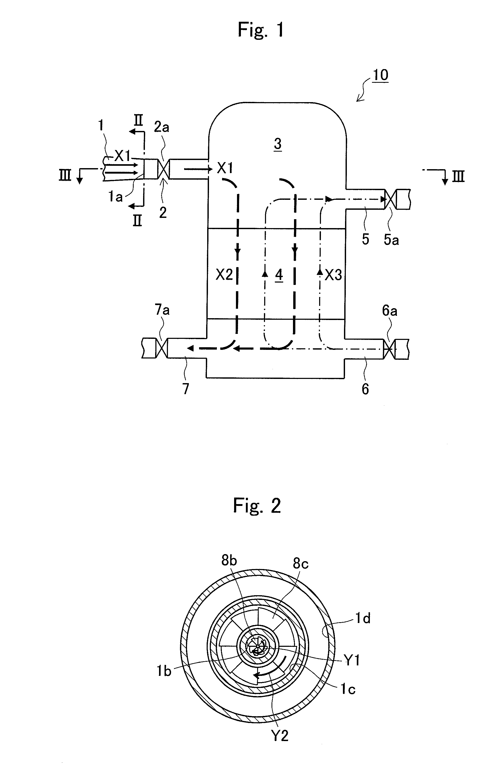
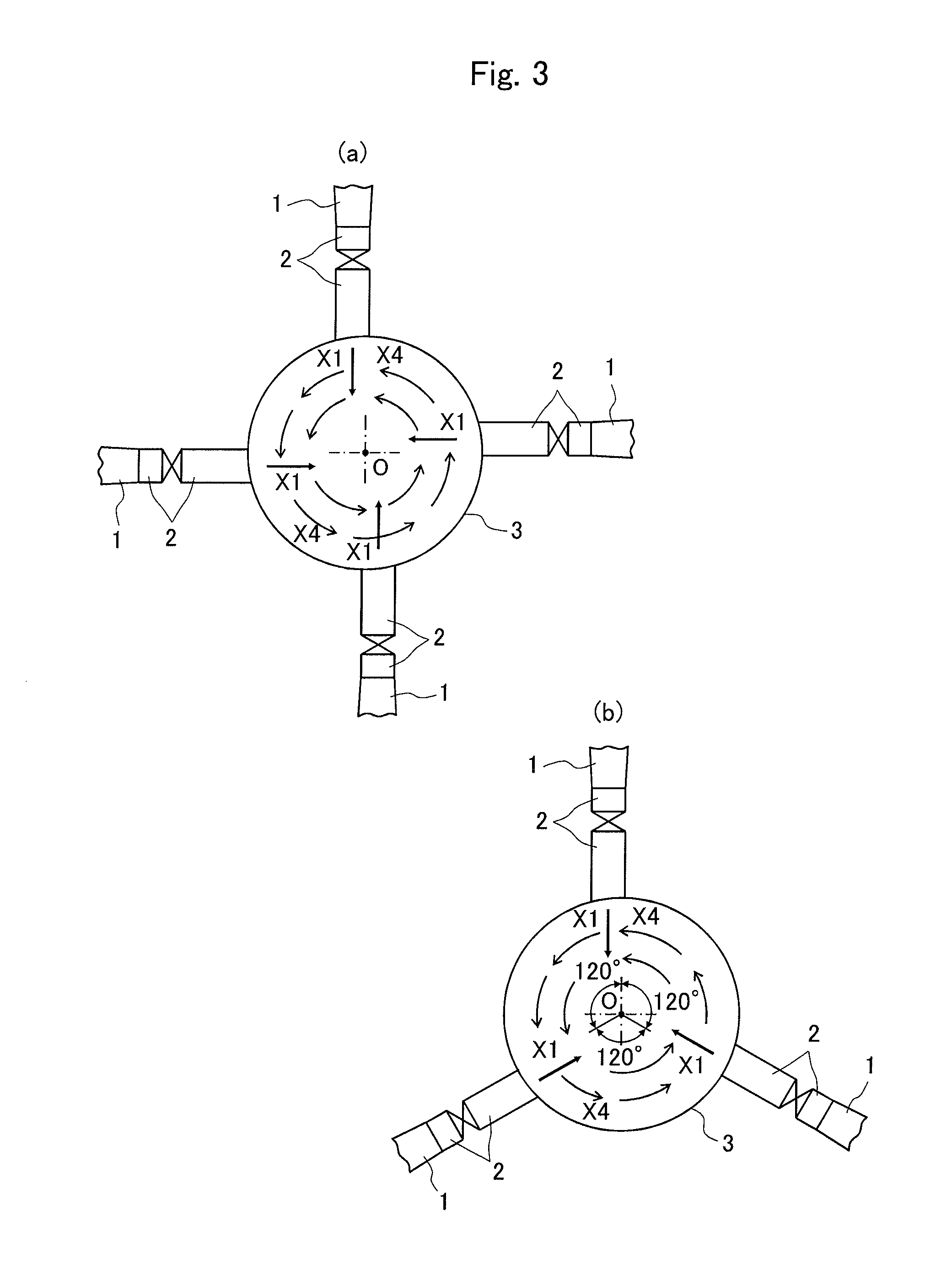
[0045]FIG. 1 is a schematic view showing one embodiment of a top-firing hot blast stove of the present invention, in which flows of mixed gas, combustion gas, hot blast air, and hot blast are illustrated together. FIG. 2 is a cross sectional view taken along arrow line II-II of FIG. 1. FIGS. 3a, 3b, 4a and 4b are cross sectional views taken along arrow line III-III of FIG. 1, each showing flows of combustion gas in a combustion chamber and showing a mounting configuration of burner systems on the combustion chamber. Further, FIG. 5 is a longitudinal sectional view of one embodiment of a burner system.

[0046]A top-firing hot blast stove 10 shown in FIG. 1 is structured in a circular form or generally circular form (such as oval forms) as a whole, and includes a combustion chamber 3 placed above a checker chamber 4. Mixed gas including fu...


PUM

PropertyMeasurementUnit
temperatureaaaaaaaaaa
diameteraaaaaaaaaa

Abstract

There is provided a top-firing hot blast stove capable of enhancing combustion efficiency in burner system, supplying high-temperature combustion gas to an entire checker chamber, and suppressing damage on a refractory material on an inner wall of a burner duct.A top-firing hot blast stove 10 has a burner system including: a burner 1 for passing fuel gas or combustion air to each of three or more pipe lines in a multiple pipe line structure; and a burner duct 2. A core pipe line 1b and a central pipe line 1c include a swirling flow generating means provided for generating a swirling flow of the fuel gas or the combustion air, while an outermost pipe line 1d carries a linear flow of the fuel gas or the combustion air, so that combustion gas HG including a linear component HG″ and a swirling component HG′ is generated in the burner duct 2. The combustion gas HG is supplied to a combustion chamber 3 from at least one or more of the burner systems in an inflow direction which does not pass through a center position of the combustion chamber 3.

Description

RELATED APPLICATIONS[0001]This application is a national stage application filed pursuant to 35 U.S.C. §371 of PCT / JP2012 / 057051, filed Mar. 19, 2012, which claims the benefit of Japanese Patent Application No. 2011-064320, filed Mar. 23, 2011, which is incorporated herein by reference in its entirety.TECHNICAL FIELD[0002]The present invention relates to a top-firing hot blast stove having a characteristic burner system.BACKGROUND ART[0003]Regenerative hot blast stoves, which generate hot blast by circulating air to a checker chamber having heat stored therein and supply the hot blast to a blast furnace, include an internal-combustion hot blast stove having both a combustion chamber and a checker chamber provided inside a cylinder shell and an external-combustion hot blast stove having a combustion chamber and a checker chamber provided in separate cylinder shells so that both the chambers communicate with each other at one ends of both the shells. As a regenerative hot blast stove ...

Claims


Application Information

Patent Timeline
Patent Type & Authority Patents(United States)
IPC IPC(8): C21B9/00C21B9/10C21B9/14F23D14/24F27B17/00
CPCC21B9/14C21B9/10F23D14/24F27B17/0083F23D2900/21001F27B2017/0091F23D14/22
Inventor MAEKAWA, NORIMASAINOUE, KOYASHIMAZU, HIROSHIKOYA, SHUNJIKUNISHIGE, NAOKIOHSHITA, NOBUHIRO
Owner NIPPON STEEL & SUMIKIN ENG CO LTD
Why Eureka
Try Eureka