
Arbitrary precision multiple description coding

a signal description and coding technology, applied in the field of signal processing, can solve the problems of waste of bandwidth in any channel, inability to use fec or crc codes otherwise to enhance the quality of reconstructed signals, and inability to achieve the effect of reducing increasing available bandwidth, and automatically increasing bit rate and signal quality

Active Publication Date: 2015-04-28
WSOU INVESTMENTS LLC
View PDF10 Cites 0 Cited by
  • Summary
  • Abstract
  • Description
  • Claims
  • Application Information

AI Technical Summary

Benefits of technology

This patent describes an improvement in coding video and other signals by using a technique called arbitrary precision multiple description coding. This coding improves bandwidth utilization by automatically adjusting the bit rate and signal quality based on the current channel conditions. This ensures that the quality of the signal remains optimal across all channel conditions. Compared to conventional approaches, this coding does not require quantization of the coefficients, which results in better signal quality and flexibility in system implementation. This is particularly useful for video transmission over wireless channels.

Problems solved by technology

However, the FEC or CRC codes are useful only for error detection and correction, and cannot otherwise be used to enhance the quality of a reconstructed signal when no errors occur.
Use of such codes therefore represents a waste of bandwidth in any channels that do not have errors.
As a result, the bit rate and signal quality may be too low for a good channel, and may be too high for a poor channel.
Therefore, such transmissions can lead to either a waste of bandwidth for good channels, or a failure to receive the signal in poor channels.
Furthermore, in some systems, the number of transmission subcarriers is required to match the number of coefficients to be transmitted, which unduly limits the applications in which such systems can be used.

Method used


Image

  • Arbitrary precision multiple description coding
  • Arbitrary precision multiple description coding
  • Arbitrary precision multiple description coding

Examples


Embodiment Construction

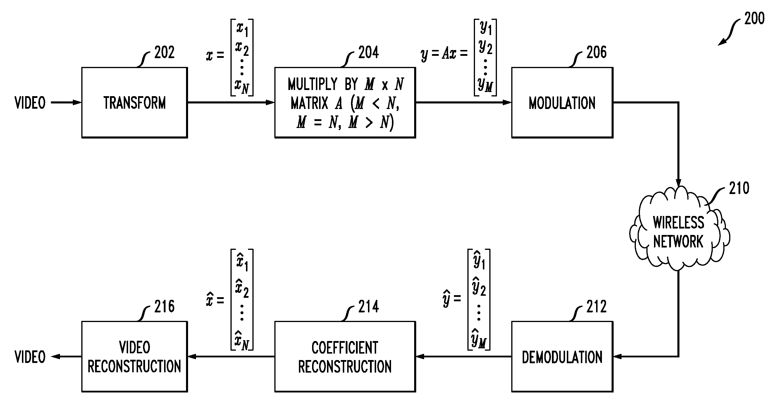
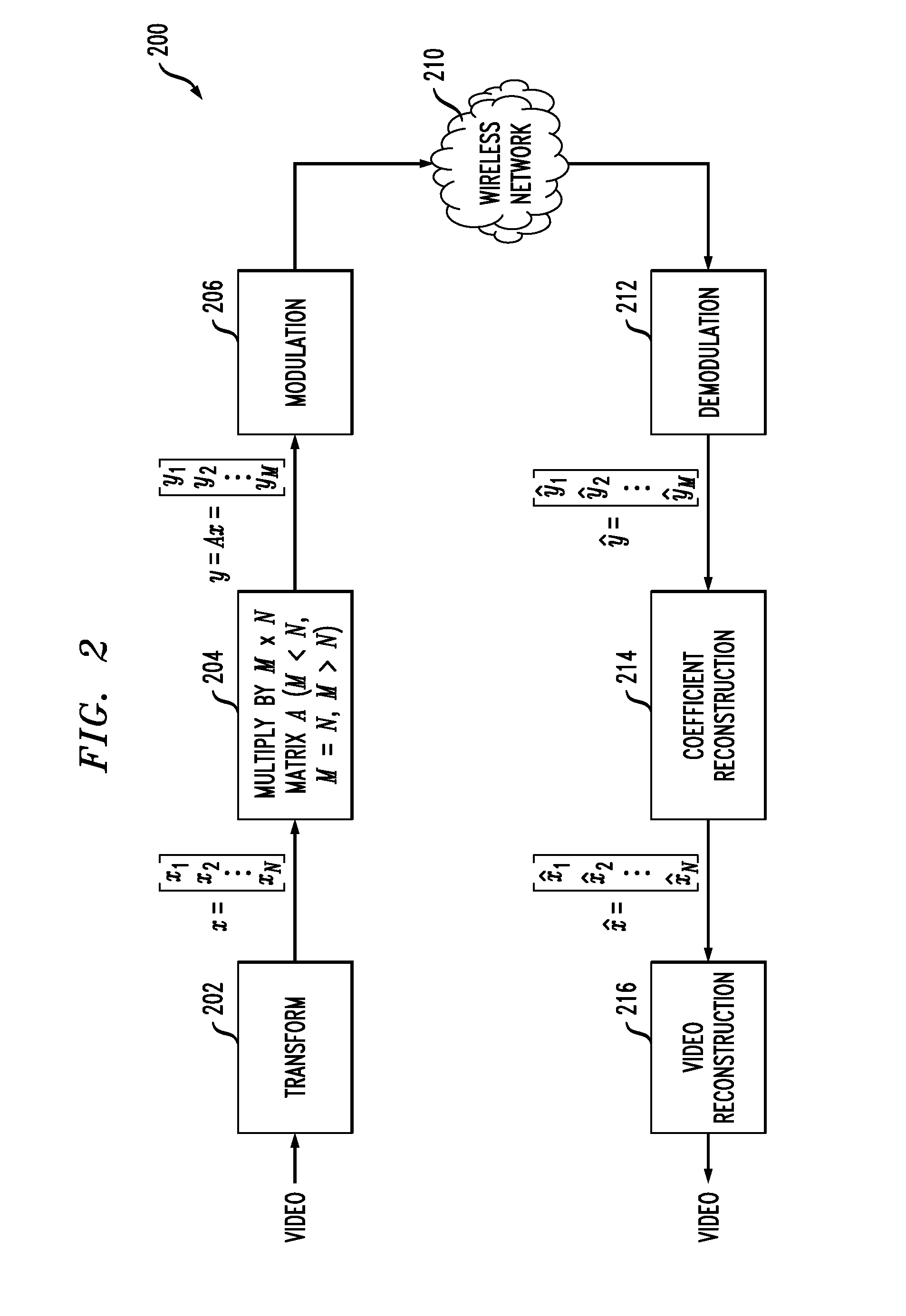
[0022]The present invention will be illustrated herein in conjunction with exemplary communication systems, processing devices and arbitrary precision multiple description coding techniques. It should be understood, however, that the invention is not limited to use with the particular types of systems, devices and techniques disclosed. For example, aspects of the present invention can be implemented in a wide variety of other communication system configurations, using processing devices and process steps other than those described in conjunction with the illustrative embodiments.

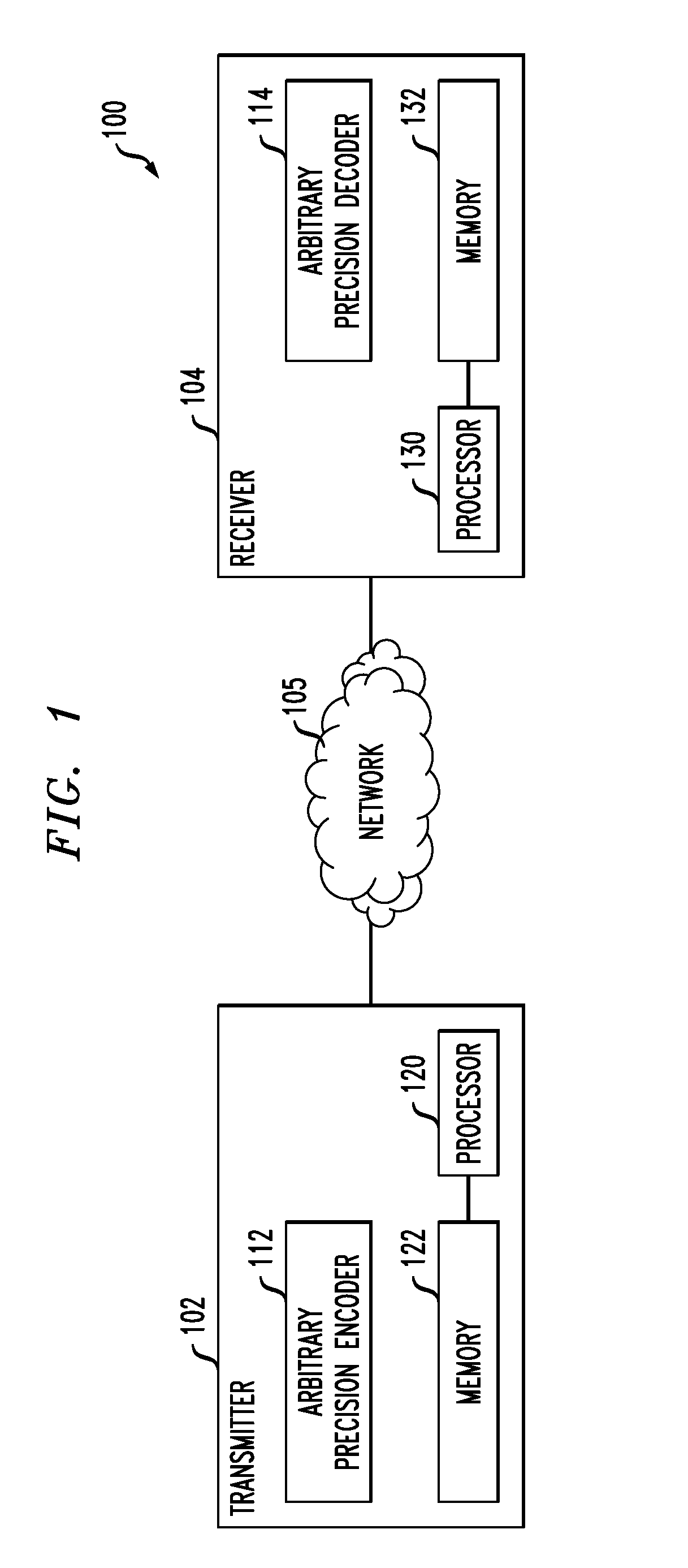
[0023]FIG. 1 shows a communication system 100 comprising a transmitter 102 coupled to a receiver 104 via a network 105. The transmitter includes an arbitrary precision multiple description encoder 112 and the receiver includes an arbitrary precision multiple description decoder 114. Also included in the transmitter 102 is a processor 120 coupled to a memory 122. Similarly, the receiver 104 comprises a proces...


PUM


Abstract

In one aspect, an encoder comprises arbitrary precision multiple description generation circuitry configured to produce multiple descriptions of a given signal by processing the signal using at least one matrix having a dimension which is selected as a function of a designated number of transmission resources, such as OFDM subcarriers or TDM time slots, that are allocated for transmission of the multiple descriptions. For example, the signal may comprise a vector x of dimension N and the arbitrary precision multiple description generation circuitry may be configured to generate M descriptions of the vector x where the value of M is selected to satisfy a particular one of three possible cases M=N, M>N and M<N depending on the number of subcarriers or time slots allocated for transmission of the multiple descriptions. Other aspects include a decoder, encoding and decoding methods, and associated computer program products.

Description

FIELD OF THE INVENTION[0001]The present invention relates generally to the field of signal processing, and more particularly relates to multiple description coding of signals for transmission over a communication network or other type of communication medium.BACKGROUND OF THE INVENTION[0002]In a typical multiple description coding arrangement, a given signal to be transmitted is processed in a transmitter to generate multiple descriptions of that signal, and the multiple descriptions are then transmitted over a network or other communication medium to a receiver. Each of the multiple descriptions may be viewed as corresponding to a different transmission channel subject to a different loss probability. The goal of multiple description coding is generally to provide a signal reconstruction quality at the receiver that improves as the number of received descriptions increases, without introducing excessive redundancy between the various multiple descriptions.[0003]One known multiple d...

Claims


Application Information

Patent Timeline
Patent Type & Authority Patents(United States)
IPC IPC(8): H04N11/04H04L1/00H04L27/26
CPCH04L1/0042H04L1/0014H04L27/2601H04L1/00H04L27/26H04N19/00
Inventor JIANG, HONGWILFORD, PAUL A.
Owner WSOU INVESTMENTS LLC
Learn More