Cyclic steam stimulation using RF

a technology of cyclic steam and rf, which is applied in the direction of fluid removal, earth-moving drilling, and well accessories, etc., can solve the problems of only being able to recover approximately 20% of the original oil in place, difficult to produce, and difficult to produce, so as to achieve sufficient heating level, reduce water consumption, and improve efficiency

Active Publication Date: 2015-05-12
HARRIS CORP +1
View PDF4 Cites 3 Cited by
  • Summary
  • Abstract
  • Description
  • Claims
  • Application Information

AI Technical Summary

Benefits of technology

[0012]The present invention provides a method of producing hydrocarbons from a well that combines CSS with RF reheating of the steam to continue the CSS process. This method realizes the important benefits of CSS, but with the improved efficiencies created by reheating the steam with RF (reducing water usage) and in some cases allowing in situ upgrading of the heavy oil when the heating level is sufficiently high.
[0013]The method begins by injecting steam into a well as in a regular SCC process. This is followed a soaking period, wherein the heat from the steam is allowed to transfer to the bitumen or heavy oil. After the soak, the heated oil is then collected. When production levels drops off, the steam that has condensed is revaporized by directing RF / MW radiation to the steam, allowing for more bitumen or heavy oil to be produced without injecting more steam. In addition, some of the steam can be superheated, thus allowing upgrading reactions to occur, and further reducing oil viscosity. Soak and production periods follow, followed by repeating the RF reheating cycle. The cyclic can be repeated until it loses its cost effectiveness. If steam is lost due to cracks in the reservoir, additional steam can be added, but assuming no losses, the CSS can be performed with a single steam injection, thus greatly conserving this precious resource.
[0021]As used herein “upgrading” refers to chemical and / or physical reactions that breaks down the hydrocarbon into molecules of lower carbon number or removes impurities from the crude oil. Through the reduction of size and removal of impurities the quality of the crude oil can be improved, thus facilitating subsequent processing and saving operational costs.
[0022]The term “hydroprocessing” may include hydrotreating, hydrocracking desulfurization, olefin and aromatic saturation / reduction, or similar reactions that involves the use of hydrogen. Through hydroprocessing the viscosity of the crude oil may be reduced, thus more readily produced and transported.

Problems solved by technology

The production of heavy oil and bitumen from a subsurface reservoirs such as oil sands or shale oil is challenging.
One of the main reasons for the difficulty is the viscosity of the heavy oil or bitumen in the reservoir.
At reservoir temperature the initial viscosity of the oil is often greater than one million centipoises, which is difficult to produce if not mobilized using external heat.
Cyclic steam stimulation or CSS was accidentally discovered by Shell while doing a steam flood in Venezuela and one of its steam injectors blew out.
However, it is typically only able to recover approximately 20% of the Original Oil in Place (OOIP), compared to steam flooding, which has been reported to recover over 50% of OOIP.
RF has also been used in various downhole applications, but to our knowledge has never been applied in a CSS method to improve CSS efficiencies.
However, this method is not a true combination of CSS and RF reheating.
Thus, the method fails realize the benefits of combining CSS with RF reheating.

Method used


Image

  • Cyclic steam stimulation using RF
  • Cyclic steam stimulation using RF
  • Cyclic steam stimulation using RF

Examples


example 1

Catalyst as Liner of Well

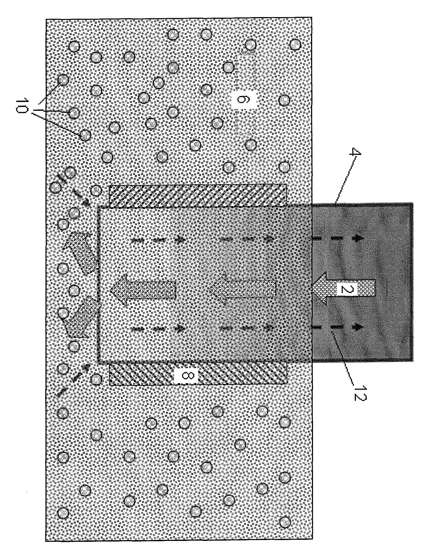
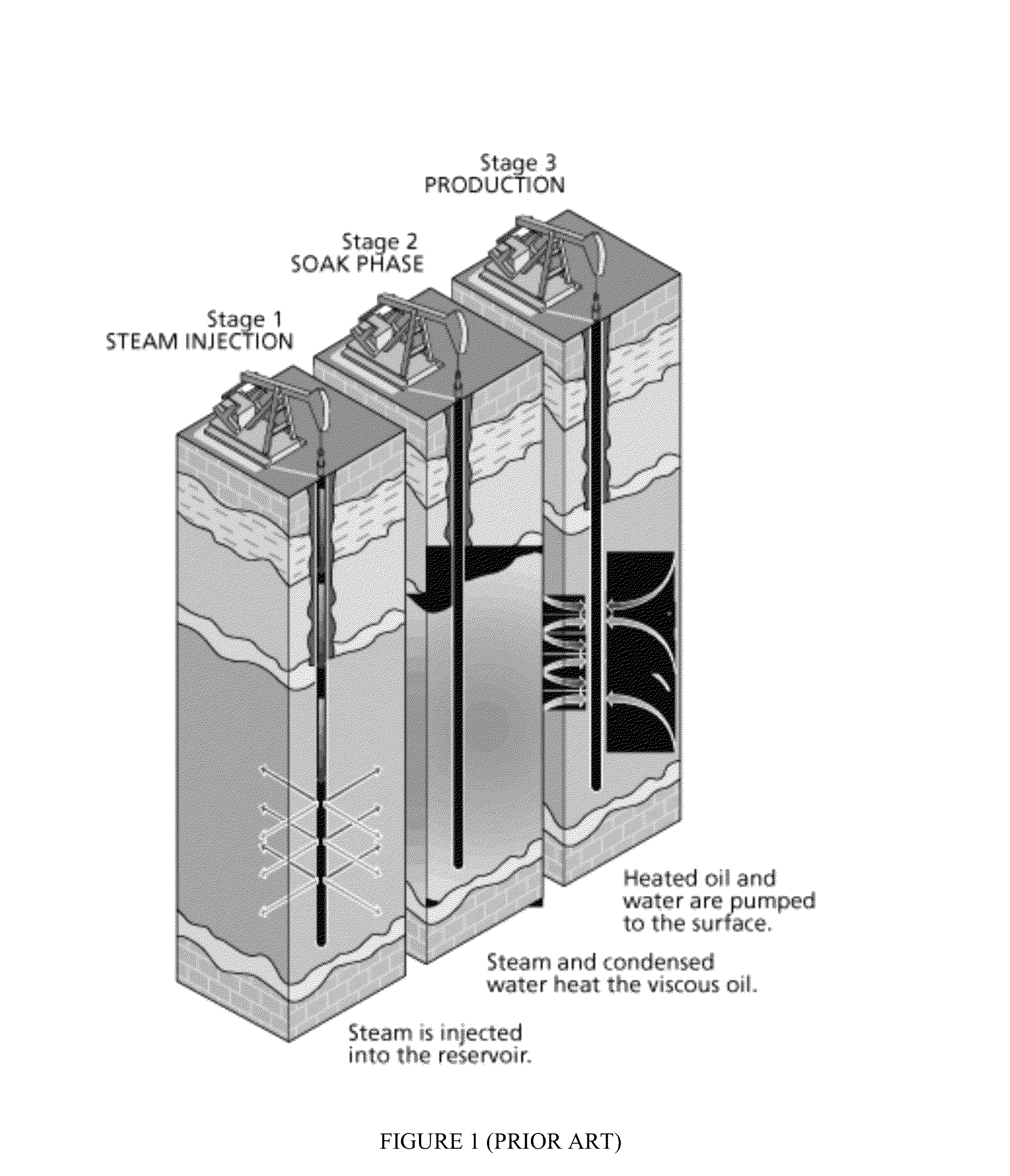
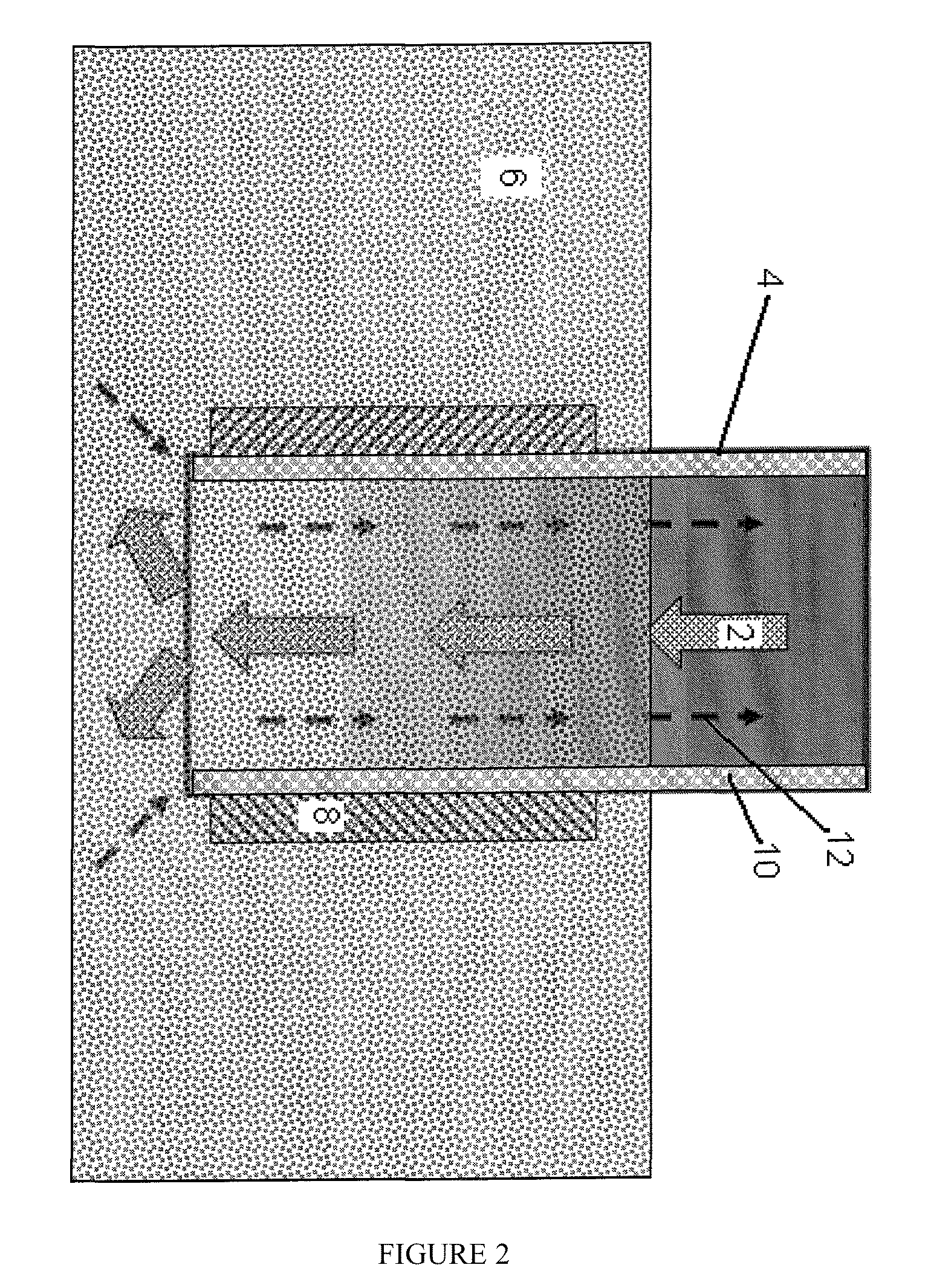
[0049]FIG. 2 describes an embodiment of cyclic steam stimulation, wherein a catalyst is placed as a liner alongside the well. In this embodiment steam 2 is injected into a well 4. The steam 2 heats the bitumen 6 in the formation. When the required temperature is achieved the injection of steam 2 into the well 4 is ceased. The bitumen 6 is soaked with the steam 2 for a period of time. MW and / or RF radiation is then directed into the well from a MW / RF antenna 8. Here the MW / RF antenna 8 is configured to surround the bottom of the well 4 so as to reheat the injected steam before the steam exits the well. The antenna can also be gusseted within the well.

[0050]In this embodiment the catalyst 10 is placed as a liner alongside the well 4. The MW and / or RF radiation is capable of heating the steam 2 into superheated steam and revaporized steam, which has a higher temperature than that of the initially injected steam. The bitumen 6 is then further heated with this su...

example 2

Catalyst in the Hydrocarbon Formation

[0051]FIG. 3 describes an embodiment of cyclic steam stimulation, wherein a catalyst is placed as particles in the hydrocarbon formation. In this embodiment steam 2 is injected into a well 4. The steam 2 heats the bitumen 6 in the formation. When the required temperature is achieved the injection of steam 2 into the well 4 is ceased. The bitumen 6 is soaked with the steam 2 for a period of time. MW and / or RF radiation is then directed into the well 4 from a MW / RF antenna 8. In this embodiment the catalyst 10 are dispersed throughout the formation. The MW and / or RF radiation is capable of heating the steam 2 into superheated steam and revaporized steam, which has a higher temperature than of the original steam. The bitumen 6 is then further heated with this superheated steam and can undergo upgrading reactions. The upgraded hydrocarbons 12 are then produced from the well 4.

example 3

Comparison of RF Reheating

[0052]FIG. 3 shows simulated results of cumulative oil SC production over time, between the a well produced with radio frequency reheating and one without the reheating. From the figure it is clearly shown that with radio frequency reheating the cumulative oil produced is much higher than that without the reheating. In fact, the well that employs radio frequency reheating can have 2,000 m3 more oil. The initial phase before reaching maximum production is also much shorter with the radio frequency reheating.

[0053]In closing, it should be noted that the discussion of any reference is not an admission that it is prior art to the present invention, especially any reference that may have a publication date after the priority date of this application. At the same time, each and every claim below is hereby incorporated into this detailed description or specification as additional embodiments of the present invention.

[0054]Although the systems and processes describ...


PUM


Abstract

A method of producing hydrocarbons from a well. The method begins by injecting steam into a well. The bitumen in the formation is then heated with the injected steam, followed by ceasing the injection of steam into the well and then by soaking the bitumen with the injected steam and collecting the heated oil. Steam that has condensed is revaporized by directing RF / MW radiation to the steam allowing for more bitumen to be produced without injecting more steam. In addition, some of the steam could become superheated, wherein the temperature of the superheated steam is greater than the temperature of the steam. The bitumen is heated by the revaporized steam and the superheated steam, followed by soaking the bitumen with the revaporized steam and the superheated steam. Hydrocarbons are then produced from the well.

Description

PRIOR RELATED APPLICATIONS[0001]This invention claims priority to U.S. Provisional Nos. 61 / 383,230 filed Sep. 15, 2010 and 61 / 466,342 filed on Mar. 22, 2011, each incorporated by reference in its entirety herein.FIELD OF THE INVENTION[0002]This invention relates to enhanced recovery techniques aimed to upgrade heavy crude oils and bitumen within the subsurface of the earth, and particularly to enhanced recovery techniques to be used with cyclic steam stimulated recovering technology that uses radio frequency heating technology to upgrade the heavy crude oils and bitumen.BACKGROUND OF THE INVENTION[0003]The production of heavy oil and bitumen from a subsurface reservoirs such as oil sands or shale oil is challenging. One of the main reasons for the difficulty is the viscosity of the heavy oil or bitumen in the reservoir. At reservoir temperature the initial viscosity of the oil is often greater than one million centipoises, which is difficult to produce if not mobilized using externa...

Claims


Application Information

Patent Timeline
Patent Type & Authority Patents(United States)
IPC IPC(8): E21B43/24
CPCE21B43/2408
Inventor MADISON, MAXINE JONESDREHER, WAYNE REIDPARSCHE, FRANCIS EUGENETRAUTMAN, MARK ALAN
Owner HARRIS CORP
Why Eureka
Try Eureka