Apparatus and method for measuring distance

a technology applied in the field of applicator and distance measurement, can solve the problems of limiting the accuracy of our knowledge, fsi is less accurate and precise than the simple method of interferometry, and interferes destructively

Active Publication Date: 2015-05-12
OXFORD UNIV INNOVATION LTD
View PDF13 Cites 20 Cited by
  • Summary
  • Abstract
  • Description
  • Claims
  • Application Information

AI Technical Summary

Benefits of technology

[0040]Provided that the two lasers are scanning differently from each other (dφ / dν≠dθ / dμ), we now have enough information to solve for both unknowns. This means that we no longer need to try to hold the distance, D, constant during the measurement, nor do we need to use a large frequency scan speed as there is no need to try to minimise the error on an estimate that dD / dν=0.
[0041]The invention thus helps to minimise or track the error that results from a change in the length of an arm during a distance measurement. That enables measurements to be made to a higher precision or, alternatively, it reduces the technical requirements of the laser used (it can have a slower scan rate and / or a smaller scan than in prior-art techniques). As discussed above, common prior-art method of minimising the problem of a changing distance during the measurement is to use tunable lasers with a rapid tuning rate (this reduces the magnification of the errors). Embodiments of the method according to the invention do not suffer from that problem, and so there is the option to use slowly tuned lasers (for example, thermally tuned DFB lasers).
[0042]The invention also provides a high measurement rate, because movement is measured continuously during each scan, and because it can cope with smaller scans without ‘movement error’ problems.

Problems solved by technology

As is well-known, waves will interfere constructively (the instantaneous amplitudes will reinforce each other) when two or more identical waves are superimposed on each other in phase (such that peaks and troughs in each wave line up with each other), and will interfere destructively (the instantaneous amplitudes will cancel each other out) when such waves are superimposed on each other in anti-phase (such that peaks and troughs in one wave line up with troughs and peaks, respectively, in another wave).
Regrettably, FSI tends to be less accurate and precise than the simple method of interferometry described above, particularly for long unknown distances.
Limits in the accuracy of our knowledge of lengths of the reference interferometer optical path difference, or the fixed laser wavelength will degrade the accuracy of the final measurement.
Therefore FSI measurements are typically less accurate than measurements with the simple method of interferometry described earlier.
Secondly, the nature of an FSI measurement is such that it is more sensitive to errors in determining the phase of the interferometers than differential interferometry is. i.e. a given error in phase measurement will lead to a larger error in distance measurement in FSI than in differential interferometry.
FSI also suffers from an error commonly known as ‘drift error’ whereby if the measured length changes during a measurement, this creates an error in the distance measurement that is typically much larger than the drift itself, being magnified by the ratio of the scan average frequency to the change in frequency over the scan.
However, the Kinder system suffered from slow recording of multiple measurements, and an improved system was developed by Bechstein K and Fuchs W, “Absolute interferometric distance measurements applying a variable synthetic wavelength”, Journal of Optics.
This method takes several sweeps for a single distance measurement and cannot compensate well for distance changes that occur on timescales shorter than the time taken for a frequency sweep.
But, prior-art FSI systems cannot cope well with a changing optical path difference (OPD).
However, in practice, FSI systems do not measure the partial derivative.
That means that prior-art FSI systems cannot simultaneously precisely determine both the absolute distance, D, and the rate of change of distance with respect to laser frequency, dD / dν.
That approximation leads to uncertainty in the measurement of D, however, which is often the dominant contribution to the overall distance measurement uncertainty in prior-art FSI systems.
Thus a drawback of current FSI measurement methods is that, if the distance measured changes (perhaps due to vibration) whilst the measurement is being made, that creates measurement errors many times larger than the scale of the movement itself.

Method used


Image

  • Apparatus and method for measuring distance
  • Apparatus and method for measuring distance
  • Apparatus and method for measuring distance

Examples


Embodiment Construction

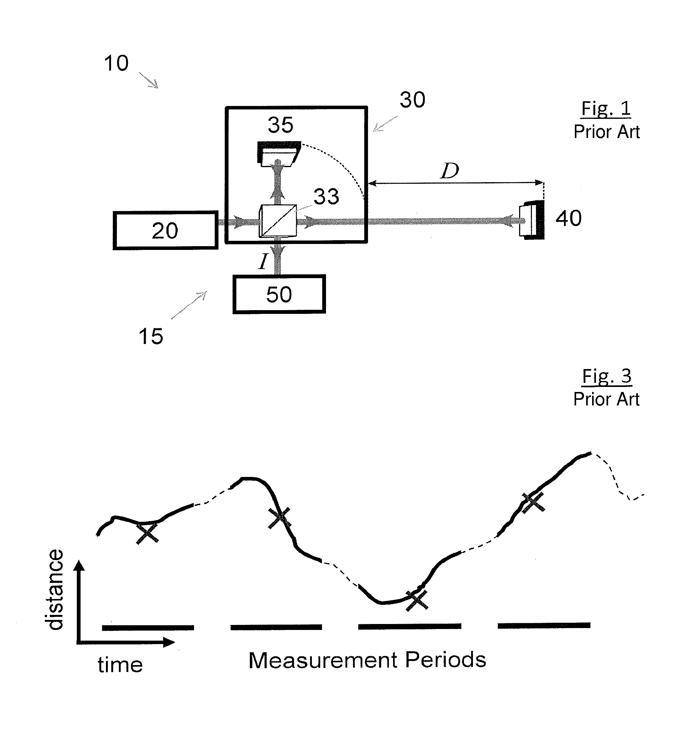
[0082]An example standard, prior-art interferometer system 10 (FIG. 1) comprises a laser 20, providing light of an intensity I0 and fixed wavelength λ. Light from the laser passes into an interferometer 15. The interferometer 15 includes an interferometer head 30. In accordance with the description given above, within the interferometer head 30 the light is split by a splitter 33, with a portion travelling a round-trip back to the splitter 33 over a known distance to a reference mirror 35. The remainder of the light travels out of the head 30, over an unknown distance to a measurement mirror 40. The light portion is reflected at mirror 40 and travels back to the splitter 33 within the head 30. The difference between the unknown distance to mirror 35 and the known distance to mirror 40 is known as the optical path difference, D. This is the distance that is to be measured. The light portion that has traveled the known distance and the light portion that has traveled to and from the m...


PUM


Abstract

A method of tracking the position of an object, comprising using reference interference data from first output beam, reference interference data from a second output beam, measurement interference data from the first output beam, measurement interference data from the second output beam, and knowledge of the difference between the absolute phase offset of the first output beam and the absolute phase offset of the second output beam for both a reference interferometer (15′) and a measurement interferometer (15) to calculate a parameter indicative of the absolute phase offset of the measurement interferometer (15) for the first output beam. The calculated parameter is used to calculate the ratio of the optical path differences of the measurement interferometer (15) and the reference interferometer (15′).

Description

[0001]This application claims the priority under 35 U.S.C. 371 of prior PCT application PCT / GB2011 / 051399, filed Jul. 22, 2011, which in turn claims the priority of prior Great Britain patent application no. 1013896.4, filed Aug. 19, 2010, all of which are incorporated herein in their entirety by reference.FIELD OF THE INVENTION[0002]The present invention concerns an apparatus and method for measuring distance. More particularly, the invention is in the field of interferometric measurement of distance.BACKGROUND TO THE INVENTION[0003]An interferometer is a well-known instrument for measuring properties of light or other waves. In its simplest form, an interferometer comprises a source of at least partially coherent waves, a splitter / combiner for splitting the waves into two portions and subsequently recombining them, two “arms” that the two split portions of waves propagate along and back prior to recombination, and a detector for detecting variations in the intensity of the recombi...

Claims


Application Information

Patent Timeline
Patent Type & Authority Patents(United States)
IPC IPC(8): G01B11/02G01B9/02G01B11/14
CPCG01B9/02004G01B9/02007G01B9/0207G01B11/14G01B2290/60
Inventor WARDEN, MATTHEWURNER, DAVID
Owner OXFORD UNIV INNOVATION LTD
Why Eureka
Try Eureka