Transmit-receive front end

a technology of transmitting and receiving, applied in the direction of low-noise amplifiers, waveguide type devices, amplifier combinations, etc., can solve the problems of sacrificing rf performance, requiring more cost and larger size on the pcb board, and lna signal loss, etc., to eliminate power loss of pa, enhance isolation from power amplifiers, and eliminate lna signal loss

Active Publication Date: 2015-05-12
MEDIATEK INC
View PDF36 Cites 18 Cited by
  • Summary
  • Abstract
  • Description
  • Claims
  • Application Information

AI Technical Summary

Benefits of technology

[0008]It is therefore an objective of the present invention to provide a transmit-receive (TR) front end utilizing a single-ended low-noise amplifier (LNA) and not utilizing a transformer to eliminate signal loss of the LNA due to a transformer, and utilizing asymmetric 2 series switches in the LNA side, to enhance isolation from the power amplifier (PA) to the LNA during a transmission interval and eliminate power loss of the PA due to a TR switch.

Problems solved by technology

However, although the prior art has flexibility to use high quality off-chip component to optimize transmission and reception performance separately, since there are many off-chip components, more cost and larger size are required on the PCB board.
On the other hand, if the prior art directly replaces those off-chip components with on-chip components, large insertion loss may occur, which sacrifices the RF performance.

Method used


Image

  • Transmit-receive front end
  • Transmit-receive front end
  • Transmit-receive front end

Examples


Embodiment Construction

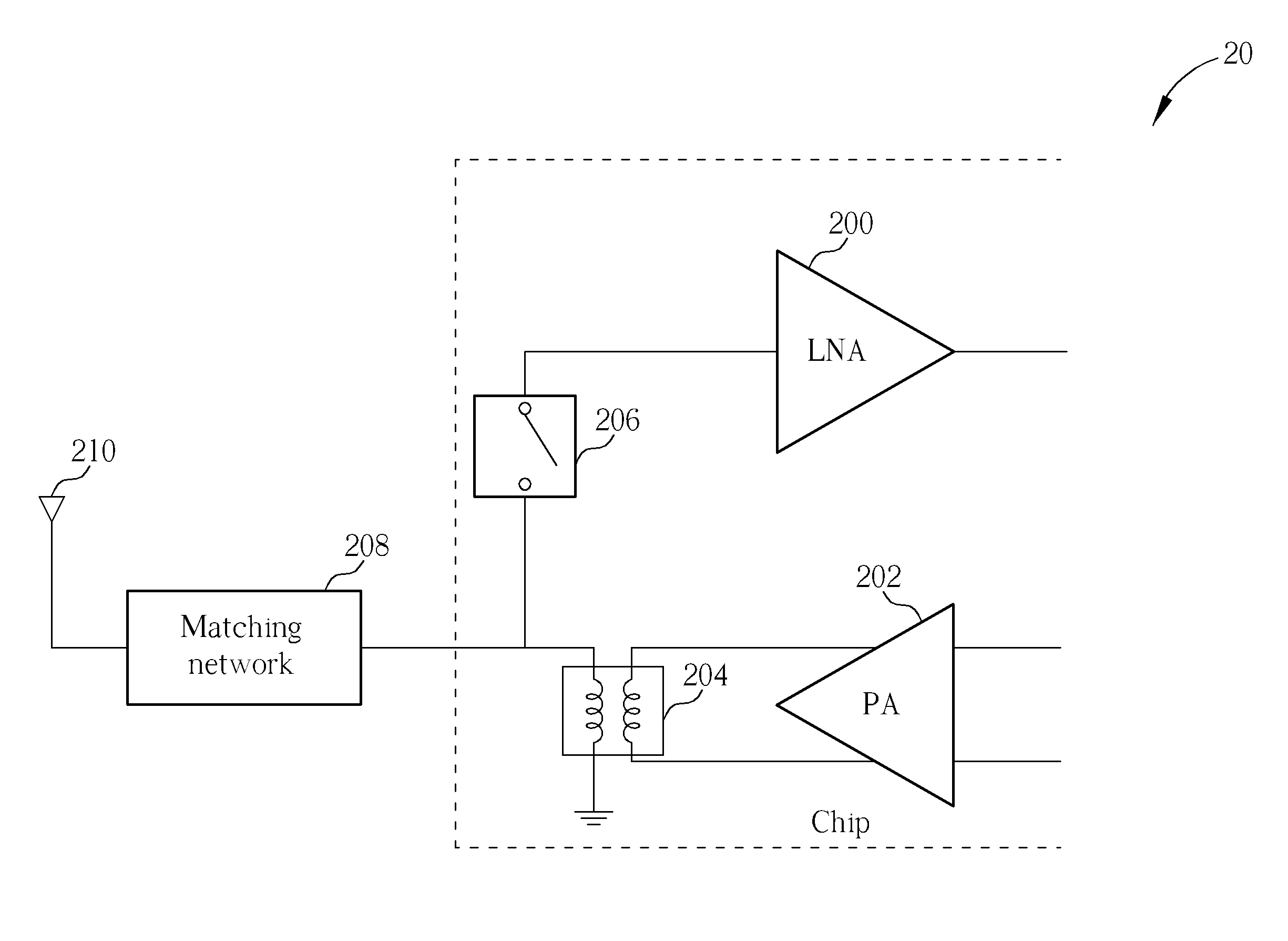
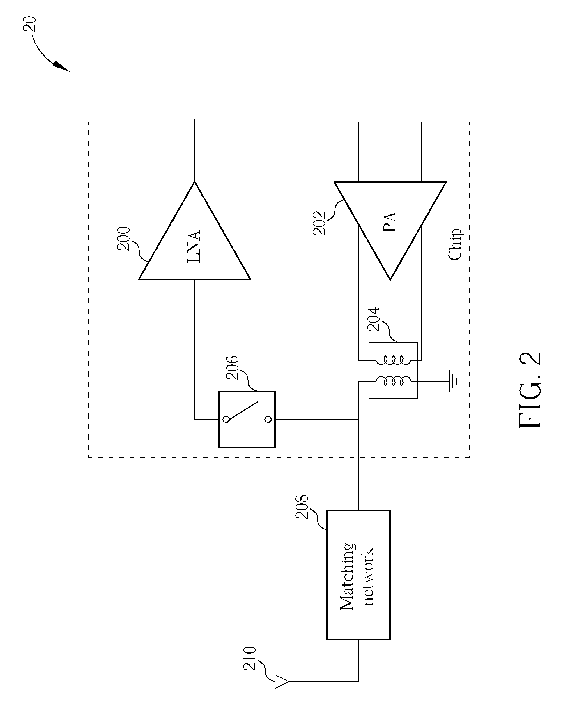
[0015]Please refer to FIG. 2, which is a schematic diagram of a transmit-receive (TR) front end 20 according to an embodiment of the present invention. As shown in FIG. 2, the TR front end 20 includes a low-noise amplifier (LNA) 200, a differential power amplifier (PA) 202, a transformer 204, a matching network 208 and an antenna 210, wherein the LNA 200, the differential PA 202 and the transformer 204 are on-chip and the matching network 208 and the antenna 210 are off-chip. As a result, most components of the TR front end 20 are on-chip, which achieves compact size, low cost and less required pins, i.e. from 4 pins to 1 pin, and are properly designed to reduce power loss of the PA 202 and signal loss of the LNA 200.

[0016]Main differences between the TR front end 20 and the TR front end 10 are that the LNA 200 is single ended and there is no transformer between the LNA 200 and the TR switch 206, the TR switch 206 is an asymmetric 2 series switches in the LNA side and thus not in a ...


PUM


Abstract

The present invention discloses a transmit-receive (TR) front end. The TR front end includes a low-noise amplifier (LNA); a power amplifier (PA); a transformer, coupled to the PA, for increasing a voltage swing and a power transmission of the PA; and a TR switch, coupled between the transformer and the LNA. The LNA is single ended and there is no transformer between the LNA and the TR switch.

Description

BACKGROUND OF THE INVENTION[0001]1. Field of the Invention[0002]The present invention relates to a transmit-receive front end, and more particularly, to a transmit-receive (TR) front end utilizing a single-ended low-noise amplifier (LNA) and not utilizing a transformer to eliminate signal loss of the LNA due to a transformer, and utilizing asymmetric 2 series switches in the LNA side, to enhance isolation from the power amplifier (PA) to the LNA during a transmission interval and eliminate power loss of the PA due to a TR switch.[0003]2. Description of the Prior Art[0004]Conventionally, a transmit-receive (TR) front end adopts many off-chip components, e.g. a transmit / receive switch, matching networks, transformers, and utilizes separate pins and matching networks for a differential low-noise amplifier (LNA) of a reception (Rx) side and a power amplifier (PA) of a transmission (Tx) side, which requires more cost and larger size on a printed circuit board (PCB).[0005]For example, ple...

Claims


Application Information

Patent Timeline
Patent Type & Authority Patents(United States)
IPC IPC(8): H04B1/44H04B1/04H04B1/18
CPCH04B1/0458H04B1/18H03F1/0205H03F3/19H03F3/245H03F2200/222H03F2200/294H04B1/44
Inventor JERNG, ALBERT CHIA-WENLI, WEN-KAILIN, CHIEN-CHENG
Owner MEDIATEK INC
Why Eureka
Try Eureka