Electric steering wheel lock device

a technology of steering wheel lock and steering wheel, which is applied in the direction of mechanical control devices, keyhole guards, instruments, etc., can solve the problems of motor drive circuit becoming non-conductive and reducing the possibility of accumulated matter

Active Publication Date: 2015-05-19
KK TOKAI RIKA DENKI SEISAKUSHO
View PDF7 Cites 0 Cited by
  • Summary
  • Abstract
  • Description
  • Claims
  • Application Information

AI Technical Summary

Benefits of technology

[0008]The present invention provides an electric steering wheel lock device that can by maintained in a satisfactory operational state.
[0010]In this structure, by changing the contact states of the relays, that is, by mechanically activating the relays, the probability of accumulated matter being removed from the relays increases. This lowers the possibility of accumulated matter causing the motor drive circuit to become non-conductive. Accordingly, an operation failure does not occur in the electric steering lock.
[0012]In this structure, when the motor drive circuit closes, the activated one of the first and second relays generates an arc due to a sudden change in potential difference. The generation of an arc removes an oxidized film from the contacts of the relay. This suppresses the obstruction of conductivity that would be caused by an oxidized film.
[0016]In this structure, an arc is generated in the relays even when the motor drive circuit is normal. This removes an oxidized film from the relays before the oxidized film obstructs conductivity. This suppresses the formation of a large oxidized film from forming on each relay. Further, when the motor drive circuit is abnormal, the contact states of the first and second relays are changed to increase the probability of accumulated matter being removed from the two relays. Then, the drive restriction unit is activated. Afterward, the contact state of one of the relays is changed to generate an arc in the relay and remove the oxidized film.
[0018]Accordingly, the present invention provides an electric steering wheel lock device that can be maintained in a satisfactory operational state.

Problems solved by technology

This lowers the possibility of accumulated matter causing the motor drive circuit to become non-conductive.

Method used


Image

  • Electric steering wheel lock device
  • Electric steering wheel lock device
  • Electric steering wheel lock device

Examples


Embodiment Construction

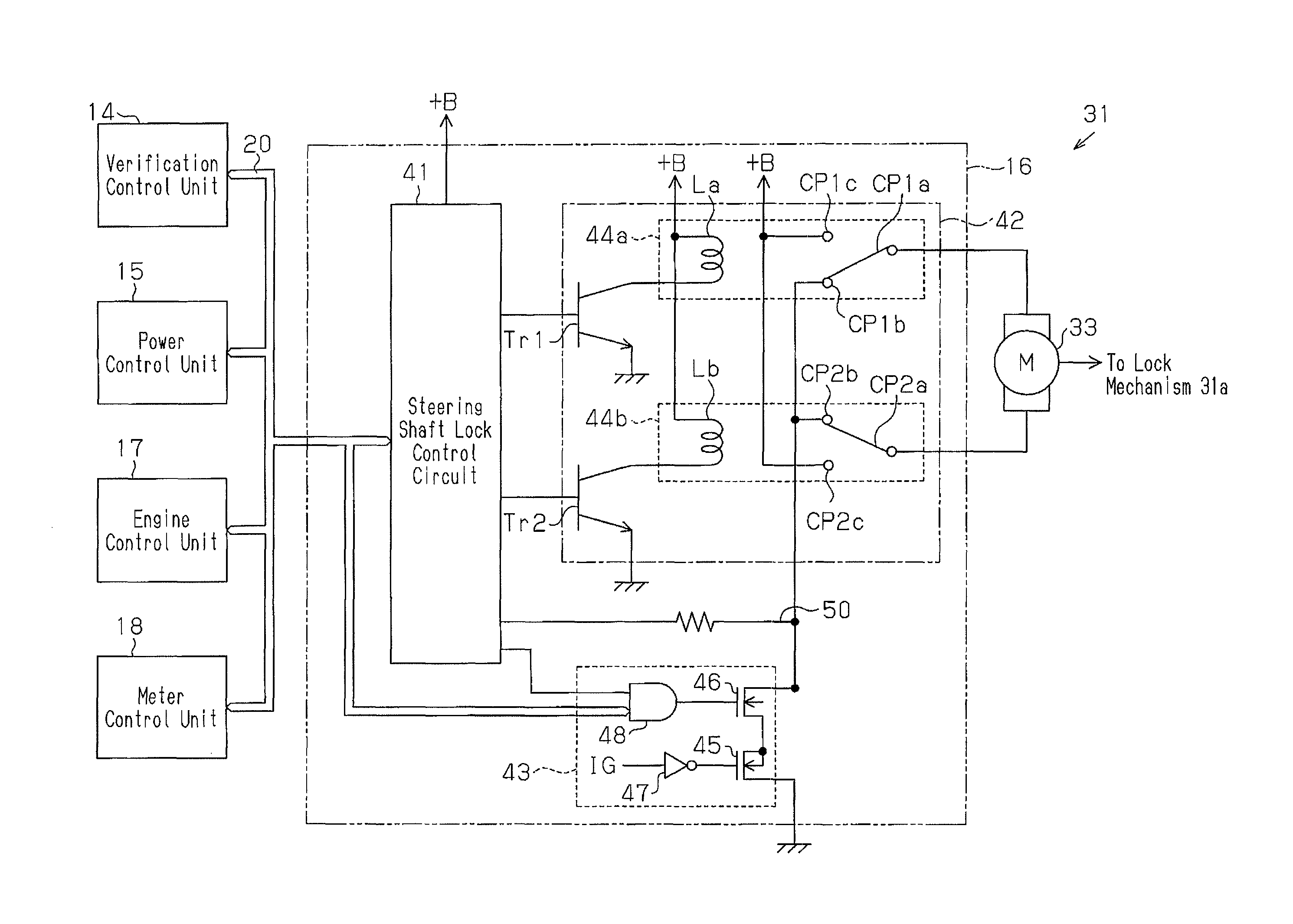
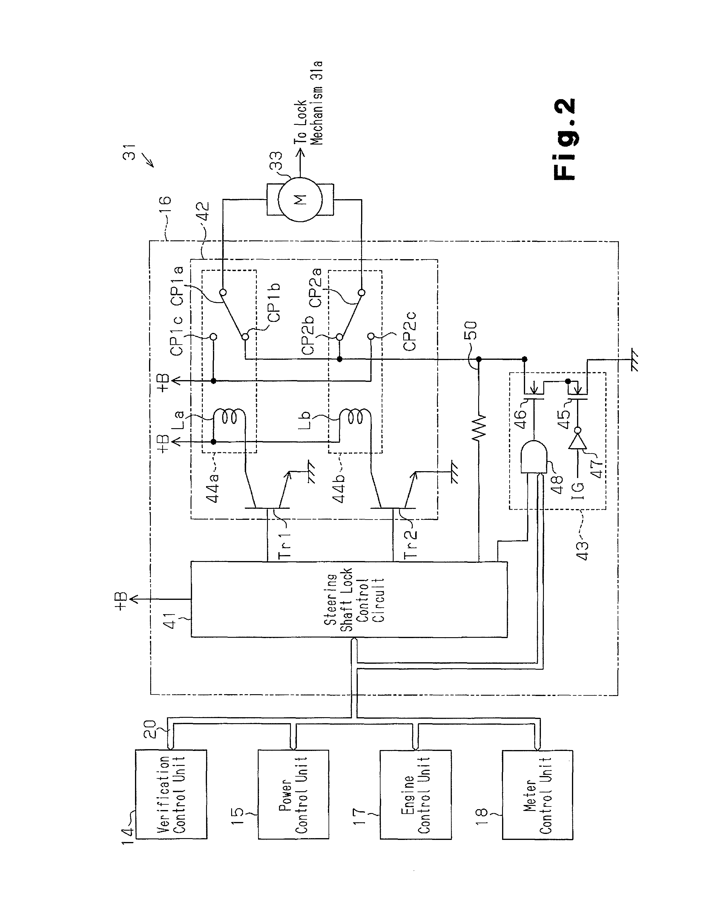
[0029]One embodiment of an electric steering wheel lock device according to the present invention will now be described with reference to FIGS. 1 to 6.

[0030]In-Vehicle Device

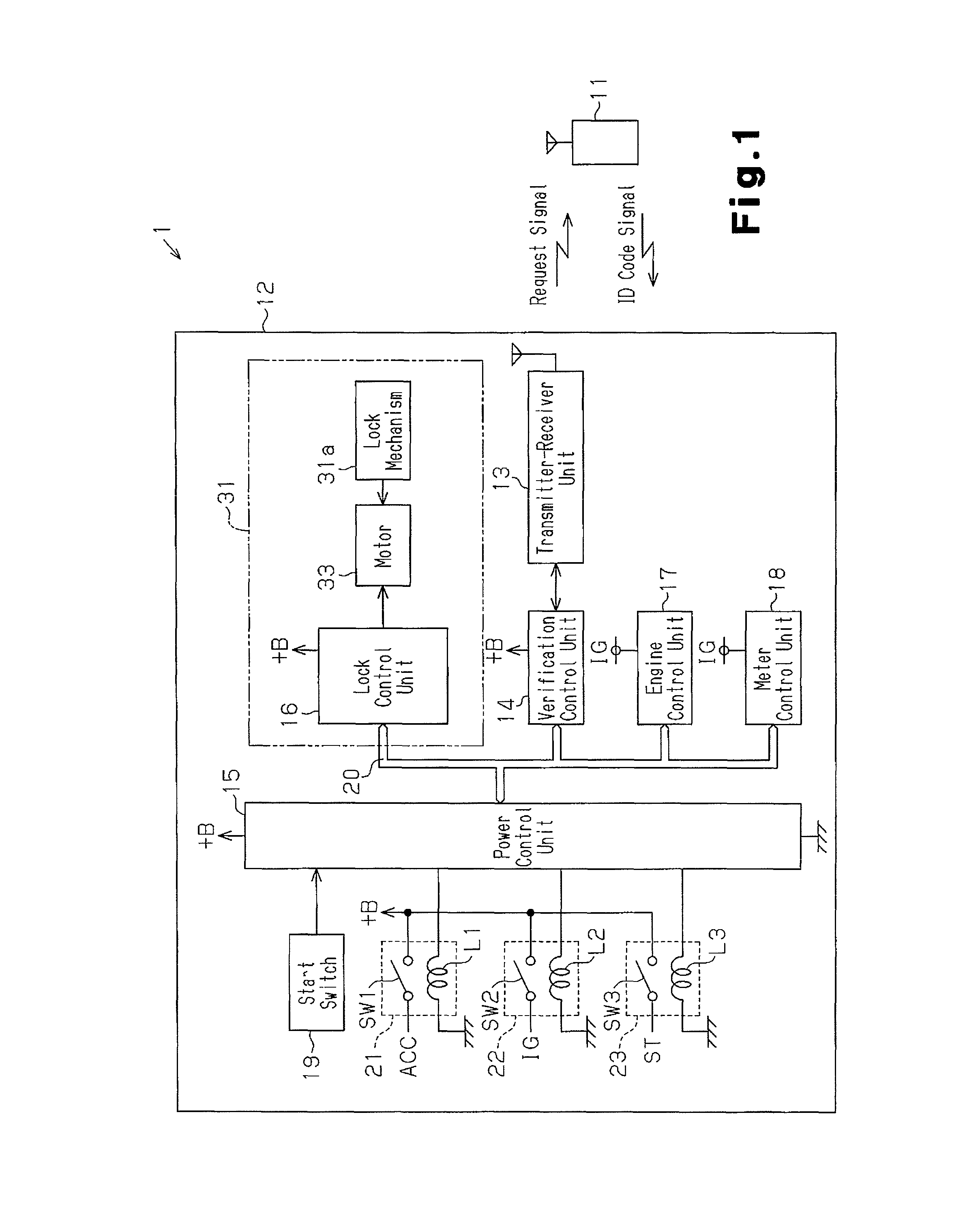
[0031]As shown in FIG. 1, an in-vehicle device 12 includes a transmitter-receiver unit 13, a verification control unit 14, a power control unit 15, a lock control unit 16, an engine control unit 17, a meter control unit 18, and a start switch 19. The controls units 14 to 18 may be central processing units (CPUs) including ROMs and RAMs. The control units 14 to 18 are connected to one another by a bus 20 and form a bus-type network. The verification control unit 14, power control unit 15, and lock control unit 16 are connected to a power supply (+B) and normally supplied with power from the power supply. The engine control unit 17, meter control unit 18, and power control unit 15 are connected to an ignition relay 22. The power control unit 15 switches the ignition relay 22 between activated and deactivated state...


PUM


Abstract

An electric steering wheel lock device includes a control circuit that starts and stops supplying power to a motor that actuates a lock mechanism to lock and unlock a movable member of a vehicle steering mechanism. The control circuit changes contact states of first and second relays to switch a supplying direction of the power. A drive restriction unit stops and starts supplying power to a drive circuit for the motor. The control circuit changes contact states of the first and second relays when the drive restriction unit stops supplying power to the drive circuit.

Description

CROSS-REFERENCE TO RELATED APPLICATIONS[0001]This application is based upon and claims the benefit of priority from prior Japanese Patent Application No. 2011-059312, filed on Mar. 17, 2011, the entire contents of which are incorporated herein by reference.BACKGROUND OF THE INVENTION[0002]The present invention relates to an electric steering wheel lock device that is electronically controlled to restrict rotation of a steering wheel.[0003]Vehicles include steering wheel lock devices to restrict rotation of a steering wheel and prevent theft. Japanese Laid-Open Patent Publication No. 2006-335321 (hereafter referred to as the '321 publication) describes an electronically controlled steering wheel lock device. The electronic steering wheel lock device includes a movable lock bar, which is engaged with a steering shaft, a motor, which moves the lock bar, and an electronic control unit, which controls the motor. The electronic control unit switches relays to switch the direction in which...

Claims


Application Information

Patent Timeline
Patent Type & Authority Patents(United States)
IPC IPC(8): B60R25/0215B60R25/24E05B47/00E05B81/64E05B83/00
CPCB60R25/02153B60R25/24Y10T70/577
Inventor KATO, HISASHI
Owner KK TOKAI RIKA DENKI SEISAKUSHO
Why Eureka
Try Eureka