Ferrite-loaded, Fabry-Perot cavity antenna

Active Publication Date: 2015-05-19
KING FAHD UNIVERSITY OF PETROLEUM AND MINERALS
View PDF11 Cites 12 Cited by
  • Summary
  • Abstract
  • Description
  • Claims
  • Application Information

AI Technical Summary

Benefits of technology

[0010]The ferrite-loaded Fabry-Perot Cavity (FPC) antenna is a novel structure, which includes magnetized ferrite cylinders optimally placed within the cavity to introduce externally controlled beam steering/shaping properties. The stepped dielectric superstrate of the FPC antenna is optimized to consid

Problems solved by technology

Although the idea of progressive phase shift introduced in the array elements works well, imp

Method used


Image

  • Ferrite-loaded, Fabry-Perot cavity antenna
  • Ferrite-loaded, Fabry-Perot cavity antenna
  • Ferrite-loaded, Fabry-Perot cavity antenna

Examples


Embodiment Construction

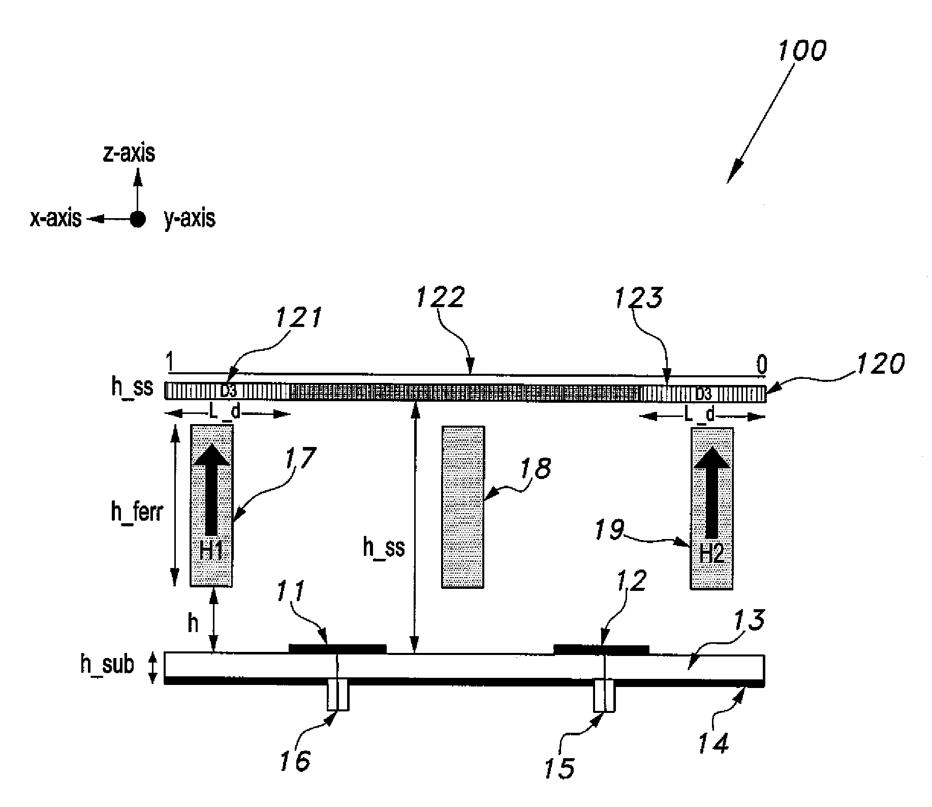
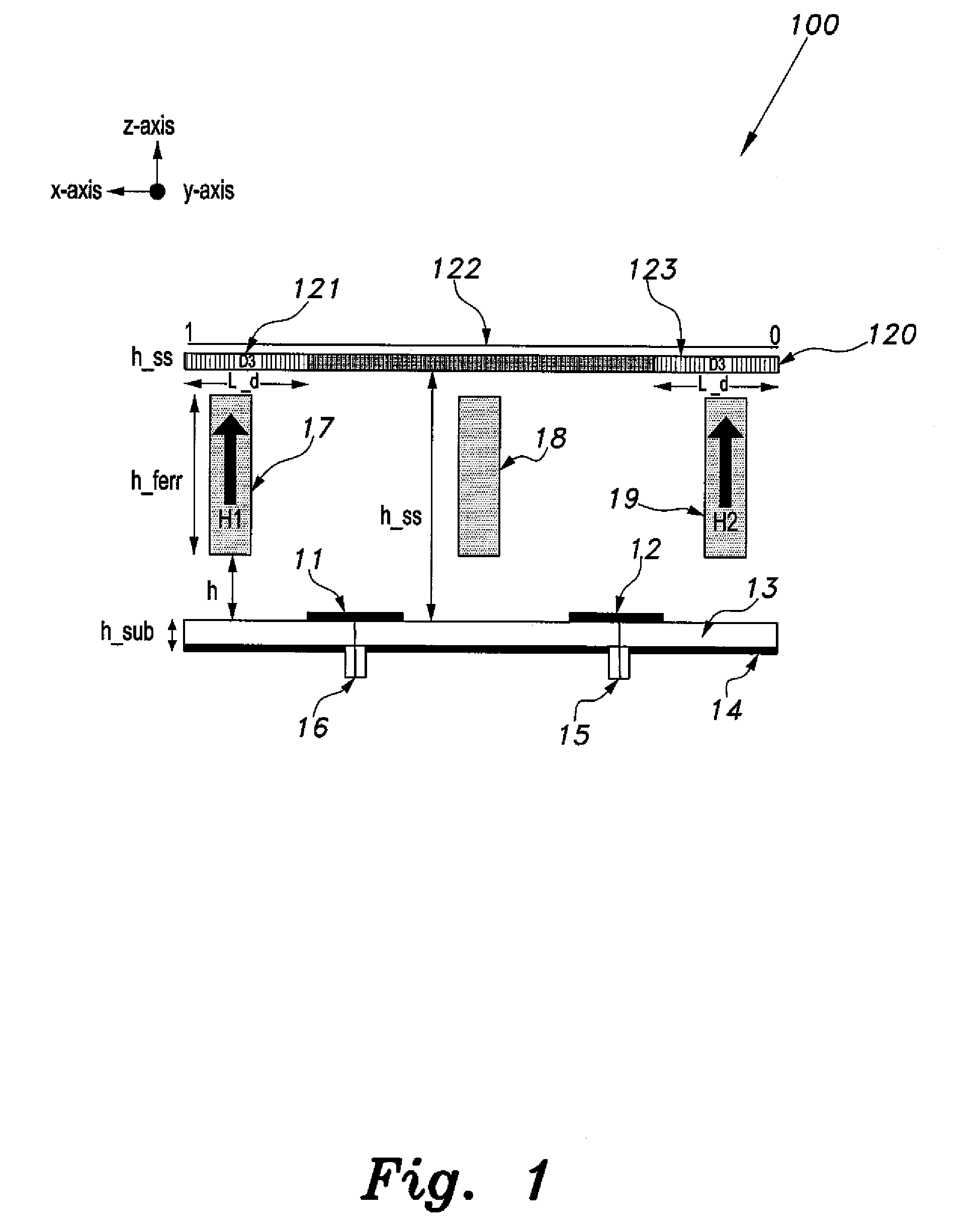
[0019]The ferrite-loaded, Fabry-Perot Cavity antenna is a novel structure that includes magnetized ferrite cylinders, optimally placed within the cavity, to introduce externally controlled beam steering / shaping properties. The partially reflecting superstate of the FPC antenna is implemented using stepped dielectric material to considerably reduce the sidelobe levels (SLL). The designed 10 GHz ferrite-loaded FPC antenna has dimensions of 6.4 cm×2 cm×1.6 cm. It achieves a −10 dB impedance bandwidth of 525 MHz, directivity of 11.04 dB and a broad side beam scanning of Δθ=±12° by varying the external magnetic biasing field ΔH=200 kA / m.

[0020]The present invention describes a directive beam shaping / steering technique, where magnetized ferrites are optimally positioned within the Fabry-Perot Cavity (FPC) to introduce desired taper in the radiated E-field phase distribution. This is achieved by exploiting the influence of the external magnetizing field on the gyromagnetic properties of fer...


PUM


Abstract

The ferrite-loaded, Fabry-Perot Cavity antenna uses a novel superstrate based beam scanning/shaping mechanism by optimally placing three magnetized ferrite cylinders within the cavity. Beam scan in a certain direction required oppositely located ferrite cylinder to be axially biased using externally controlled DC magnetizing field. The FPC utilizes a composite dielectric superstrate to inversely relate the mainlobe-to-sidelobe ratio with scan-angle, which demonstrates larger reduction in side lobe level with increases angle of beam scan. The designed 10 GHz ferrite-loaded FPC antenna has dimensions of 6.4 cm×2 cm×1.6 cm. It achieves a −10 dB impedance bandwidth of 525 MHz, directivity of 11.04 dB and a broadside beam steering range of ±12° for 200 kA/m (0.25 T) changes in the externally applied axial magnetizing field.

Description

BACKGROUND OF THE INVENTION[0001]1. Field of the Invention[0002]The present invention relates to antennas, and particularly to a ferrite-loaded, Fabry-Perot Cavity antenna that achieves a −10 dB impedance bandwidth of 525 MHz, directivity of 11.04 dB, controlled side lobe level and a phase shifter less broadside beam scanning of ±12° for 200 kA / m changes in the externally applied axial magnetizing field.[0003]2. Description of the Related Art[0004]The use of radars in the aviation industry has had a long history. Traditional radar systems radiate a high-power signal at a certain frequency, and point it towards a desired direction. Historically, the radar antenna was mechanically rotated to cover the complete 360° azimuth plane and the reflected signals from the targets illuminated by the radar beam were monitored to locate the targets. As the antenna fabrication and microcontroller technology progressed, electronic beam scanning came into being. In a uniform phased array antenna, th...

Claims


Application Information

Patent Timeline
IPC IPC(8): H01Q1/38H01Q9/04
CPCH01Q9/0407H01Q1/38H01Q3/2623H01Q21/08
Inventor MITU, SHEIKH SHARIF IQBALSULTAN, FAROOQMITTRA, RAJ
Owner KING FAHD UNIVERSITY OF PETROLEUM AND MINERALS
Why Eureka
Try Eureka