
Chirped pulse frequency-domain comb for spectroscopy

Active Publication Date: 2015-06-02
UNIV OF VIRGINIA ALUMNI PATENTS FOUND
View PDF20 Cites 16 Cited by
  • Summary
  • Abstract
  • Description
  • Claims
  • Application Information

AI Technical Summary

Benefits of technology

This patent describes a new approach to microwave spectroscopy using frequency-domain combs generated by a solid-state electronic apparatus. This approach allows for the efficient and accurate detection of rotational spectroscopy in molecules, which is difficult to achieve using traditional methods. The use of frequency-domain combs eliminates the need for mode-locked lasers and allows for the measurement of molecules over a wide range of frequencies. The technical effects of this patent include improved sensitivity, reduced measurement time, and improved analytical chemistry applications.

Problems solved by technology

Microwave spectrometers, such as using a waveguide, generally limit the size range of molecules that can be interrogated by pure rotational spectroscopy, such as because of the need for sufficient vapor pressure in the waveguide cell.
For example, the use of a cavity with high quality factor generally limits the measurable frequency bandwidth to less than 1 megahertz (MHz) in generally-available spectrometer designs.
However, the process of acquiring a spectrum over the full operating range of the spectrometer is laborious.
A spectrum spanning a frequency range of several GHz can be obtained, but the Fabry-Pérot spectrometer design leads to long spectrum acquisition times (e.g., many hours).
The time-consuming spectral acquisition process poses difficulties for using FTMW spectroscopy in analytical chemistry applications, for optimizing source conditions for previously unknown species, or for performing rotational spectroscopy of excited vibrational or electronic states prepared by laser.
The main difficulties with the mode-locked laser approach include the low pulse energies associated with individual frequency-domain combs and the non-robust nature of the basic laser light sources.
Such laser-based approaches face challenges in extending operation into desired ranges of frequencies, such as into the chemically important frequency range of between about 3-30 terahertz (THz).

Method used


Image

  • Chirped pulse frequency-domain comb for spectroscopy
  • Chirped pulse frequency-domain comb for spectroscopy
  • Chirped pulse frequency-domain comb for spectroscopy

Examples


example 1

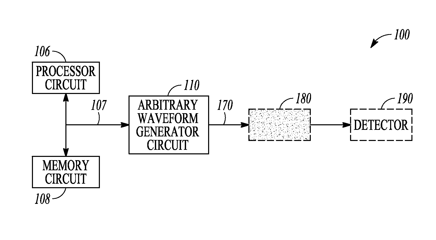
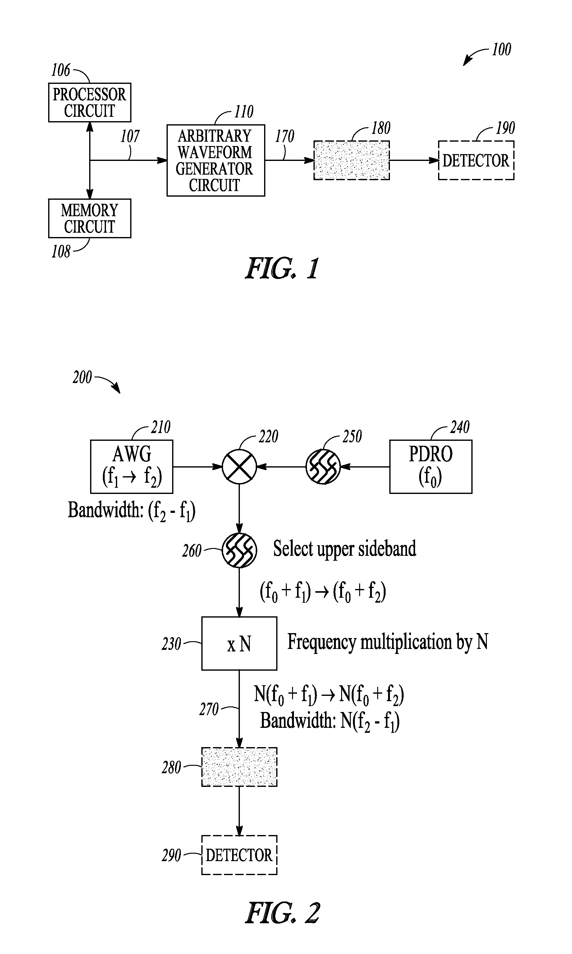
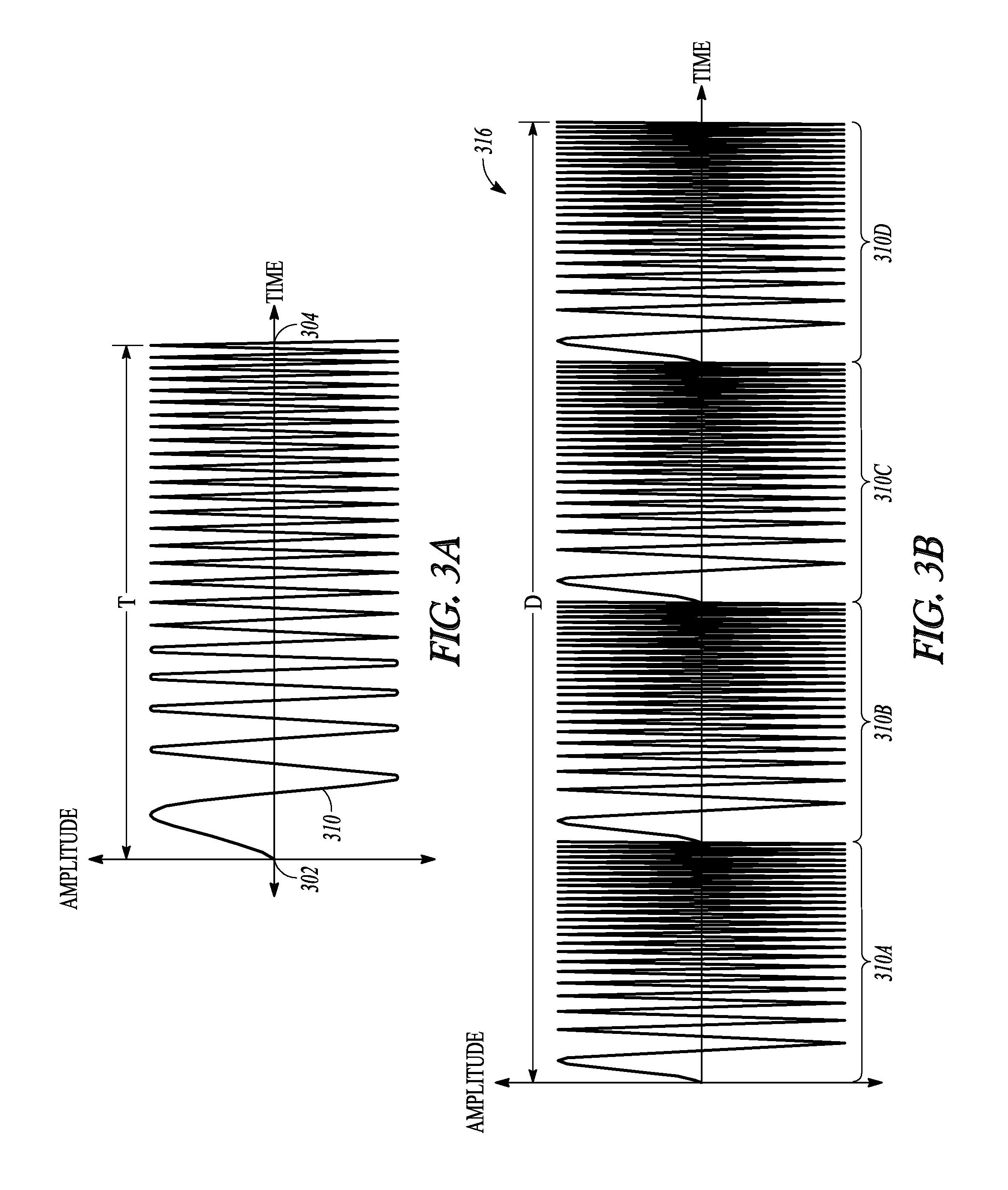
[0079 includes subject matter, (such as a method, a means for performing acts, or a machine readable medium including instructions, that, when performed by the machine, cause the machine to perform acts) comprising generating a pulse train comprising chirped pulses of electromagnetic energy, the respective chirped pulses including a frequency sweep across a first specified bandwidth during a respective chirped pulse duration, the respective chirped pulse duration establishing a first frequency-domain comb peak separation, and exciting a sample using the pulse train. In Example 1, a width of a frequency-domain comb peak is established at least in part by a total duration of the pulse train, and a bandwidth of a first frequency-domain comb is determined at least in part by the first specified bandwidth of the frequency sweep of the respective chirped pulses.

[0080]In Example 2, the subject matter of Example 1 can optionally include a pulse train comprising chirped pulses respectively s...


PUM


Abstract

A pulse train comprising chirped pulses of electromagnetic energy can be used to excite a sample, such as for spectroscopic analysis. The respective chirped pulses can include a frequency sweep across a first specified bandwidth during a respective chirped pulse duration, the respective chirped pulse duration establishing a first frequency-domain comb peak separation. A width of a frequency-domain comb peak can be established at least in part by a total duration of the pulse train, and a bandwidth of the first frequency-domain comb can be determined at least in part by the first specified bandwidth of the frequency sweep of the respective chirped pulses.

Description

CLAIM OF PRIORITY[0001]This application is a U.S. National Stage Filing under 35 U.S.C. §371 from International Patent Application Ser. No. PCT / US2011 / 040876, filed on Jun. 17, 2011, and published on Dec. 22, 2011 as WO 2011 / 160013 A1, which claims the benefit of priority of U.S. Provisional Patent Application Ser. No. 61 / 355,862, entitled “Chirped Pulse Frequency-domain combs (CPFC) for Spectroscopy from Microwave to Infrared,” filed on Jun. 17, 2010, the benefit of priority of each of which is claimed hereby, and each of which is hereby incorporated by reference herein in its entirety.STATEMENT REGARDING FEDERALLY SPONSORED RESEARCH OR DEVELOPMENT[0002]This invention was made with government support under Grant No. CHE-0215957 (MRI Program), CHE-0618755 (CRIF: ID Program), and CHE-0847919 (CCI Program), awarded by the Chemistry Division (CHE) of the National Science Foundation (NSF). The government has certain rights in the invention.BACKGROUND[0003]Spectroscopy, such as rotationa...

Claims


Application Information

Patent Timeline
IPC IPC(8): G01J3/30G01N21/3586G01N22/00H01S3/00
CPCG01N22/00G01N21/3586H01S3/0057G01J3/10G01J3/4338G01J3/44G01N21/31G01N21/62G01N21/67G01N21/69
Inventor PATE, BROOKS HARTLEHMANN, KEVIN K.
Owner UNIV OF VIRGINIA ALUMNI PATENTS FOUND
Learn More