
Micromechanical structure comprising a mobile part having stops for out-of plane displacements of the structure and its production process

a technology of micromechanical structure and mobile parts, applied in the direction of instruments, loudspeakers, acceleration measurement using interia forces, etc., can solve the problems of inability to control the symmetry between high and low stops, particularly harmful to the low limit, and inability to optimize the performance of the mems and its bulk

Active Publication Date: 2015-06-23
COMMISSARIAT A LENERGIE ATOMIQUE ET AUX ENERGIES ALTERNATIVES
View PDF22 Cites 4 Cited by
  • Summary
  • Abstract
  • Description
  • Claims
  • Application Information

AI Technical Summary

Benefits of technology

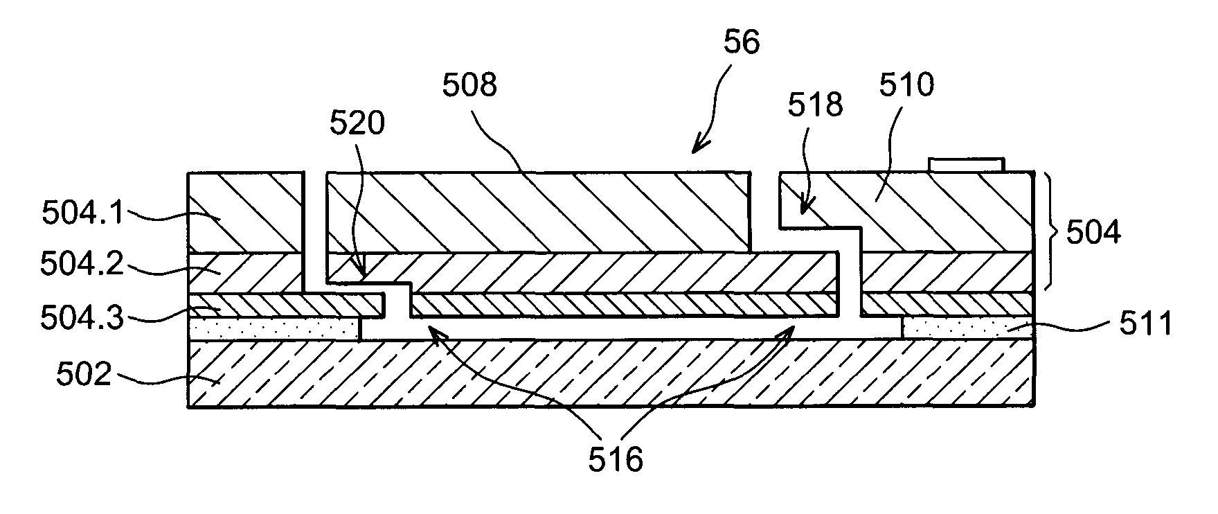
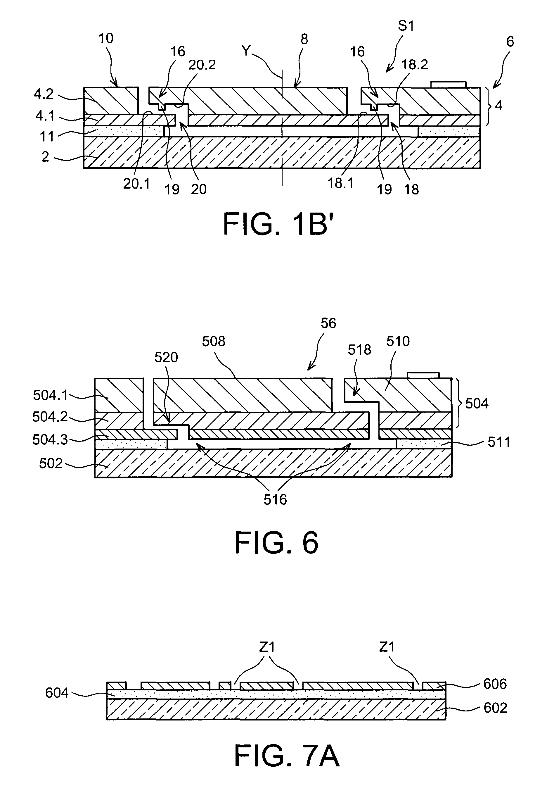
The present invention provides a simplified production process for a MEMS or NEMS system with an active structure formed by a stack of layers on a substrate of a mobile part and a fixed part. The mobile part can be released without the need for protection by encapsulation, and vertical releasing is achieved through a simple step of photolithoetching. The opposite faces of the active structure can form stops for limiting out-of-plane movements and reducing risks of sticking. The making of stops within the active structure results in considerable control of the value of the gap obtained by deposit of a thin layer.

Problems solved by technology

However, producing these stops means that the gap between the stop and the mobile element is directly dependent on the MEMS / cover or MEMS / substrate gap.
This lower limit is particularly harmful in the case of highly rigid structures, of sensor type with strain gauge detection, for example of piezoresistive gauge or resonator type, which tolerate only minor displacements of the mobile part.
The performances of the MEMS and its bulk are therefore not optimal.
It is not possible to control the symmetry between high and low stops.
Now processes of the prior art for making out-of-plane MEMS and NEMS sensors or actuators are complex, long and costly.
Apart from this, the complexity of the production process, the dimensions of the vertical gaps are considerably limited by the process itself.
In addition, this architecture limits the choice of dimensions of the vertical and horizontal gaps and the active part, since they are interdependent.

Method used


Image

  • Micromechanical structure comprising a mobile part having stops for out-of plane displacements of the structure and its production process
  • Micromechanical structure comprising a mobile part having stops for out-of plane displacements of the structure and its production process
  • Micromechanical structure comprising a mobile part having stops for out-of plane displacements of the structure and its production process

Examples


Embodiment Construction

[0099]Throughout the description, the micromechanical structures described are adapted to making an accelerometer, but it is well understood that the present invention applies to making any other type of sensor, for example making gyrometers and or any other system using such a micromechanical structure.

[0100]In the description, MEMS designates both micro-electro-mechanical systems and nano-electro-mechanical systems.

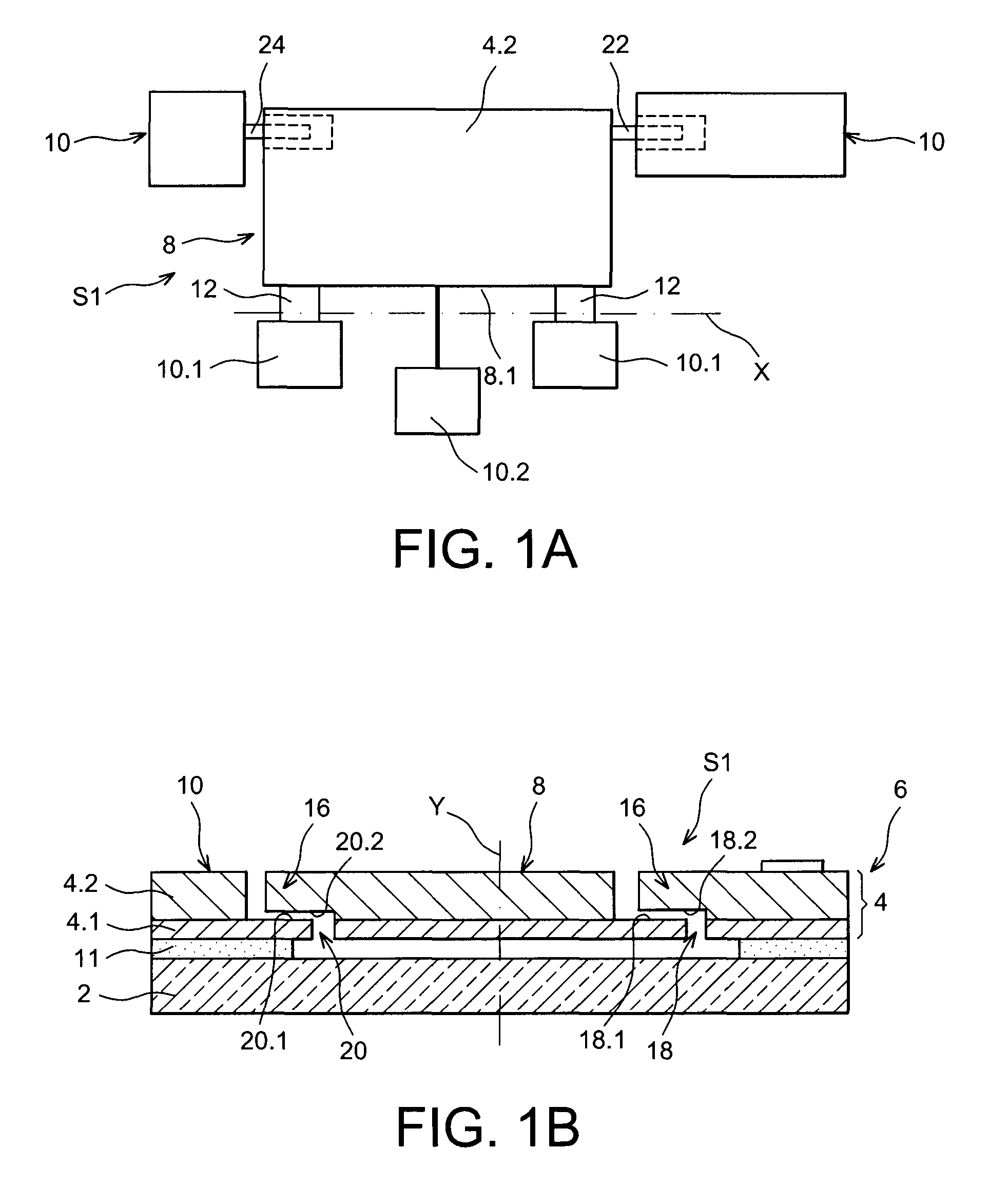
[0101]FIGS. 1A and 1B illustrate a first example of a micro-electro-mechanical structure for making an out-of-plane accelerometer with strain gauge.

[0102]A micromechanical structure is called out of plane when the direction of displacement of its mobile part is oriented substantially perpendicularly to its principal plane.

[0103]The micromechanical structure S1 of FIGS. 1A and 1B comprises a substrate 2, on which is arranged a stack 4 of at least two layers 4.1, 4.2, in the example shown.

[0104]The stack 4 forms the active structure of the micromechanical structure, the a...


PUM

PropertyMeasurementUnit
heightsaaaaaaaaaa
heightsaaaaaaaaaa
heightsaaaaaaaaaa

Abstract

A process for producing a micromechanical structure including a substrate and a stack of at least two layers arranged on the substrate is provided. A mobile part is formed in the stack and a fixed part relative to the substrate is formed in the stack, and an opposite surface is formed between the fixed part and the mobile part, to present a stop device to limit displacement of the mobile part in a direction substantially perpendicular to the stack. The process uses at least one sacrificial layer between the substrate and the stack made of material suitable to be etched selectively relative to the materials of the stack.

Description

TECHNICAL FIELD AND PRIOR ART[0001]The present invention relates to micro-electro-mechanical systems or MEMS (Micro-Electro-Mechanical Systems) and to nano-electro-mechanical systems or NEMS (Nano-Electro-Mechanical Systems).[0002]These systems comprise an active structure composed of a fixed element and a mobile element, the mobile element being suspended relative to the fixed element and able to move relative to the fixed element. The fixed element is deposited on a substrate and the active structure is covered with a protective cover.[0003]These systems can be used as sensors, for example as an accelerometer, gyrometer, magnetometer, etc. The mobile element or suspended mass is set in motion by external forces; its displacement relative to the fixed element is measured, for example in the form of a variation in capacity. These measurements deduce variations in acceleration of a vehicle for example.[0004]The mobile element is therefore intended to move, in a plane and / or out of pl...

Claims


Application Information

Patent Timeline
Patent Type & Authority Patents(United States)
IPC IPC(8): B81C1/00B81B3/00G01P15/08G01P15/125
CPCB81C1/00476B81B3/0051B81C1/00984G01P15/0802G01P15/125H04R2201/003G01P2015/0817G01P2015/0871
Inventor ROBERT, PHILIPPEWALTHER, ARNAUD
Owner COMMISSARIAT A LENERGIE ATOMIQUE ET AUX ENERGIES ALTERNATIVES
Learn More