Spinal facet fixation device

a fixation device and spine technology, applied in the field of screws, can solve the problems of affecting the healing effect of the spine, etc., and achieve the effect of preventing loosening of the device over time and increasing compression

Active Publication Date: 2015-07-07
THE CENT FOR ORTHOPEDIC RES & EDUCATION
View PDF28 Cites 12 Cited by
  • Summary
  • Abstract
  • Description
  • Claims
  • Application Information

AI Technical Summary

Benefits of technology

[0012]Described below is a cannulated and partially threaded bone screw assembly for the fixation of a spinal facet joint. The assembly is inserted through a very small incision near the facet joint, and has a feature that provides for the expansion of the portion of the device protruding through the superior facet of the inferior vertebrae. The expansion feature, along with the partially threaded screw shaft, serve to increase compression between the facet joint surfaces and also prevent loosening of the device over time.
[0013]In one preferred embodiment the device comprises three parts which can move with respect to one another. The three parts are an outer screw shank, an inner screw shank, and a tip. The inner shank is disposed within the outer shank. The external surface of the outer shank is partially threaded at the distal end. The external surface of the inner shank is partially threaded at the distal end, such that the distal end of the inner shank secures the tip to the screw assembly. The external surface of the tip is fully threaded. Additionally, the internal surface of the tip is threaded at the proximal end such that the inner shank can screw into the tip. Once the outer shank is positioned such that it extends through the bones, the outer shank is held stationary and the inner shank is turned. The tip is drawn into the outer shank via the threads on the inner shank which causes the outer shank to deform. The deformation caused by the tip serves to increase the size of the outer shank such that it becomes larger in diameter than the hole through which it was inserted. The deformation increases the compressive force across the facet joints and also prevents the screw from loosening or backing out of the hole through which it was inserted.

Problems solved by technology

Without a specific way to prevent loosening of the device, loosening will likely occur as the result of micromotion.
Once a device has loosened, the device will often begin to protrude from or back-out of the bone, causing significant discomfort, damage to the joint, or danger to surrounding tissues.
However, each previously proposed fixation device has suffered significant shortcomings.
However, a fully threaded screw is not capable of creating any significant amount of compression between two bone surfaces.
Further, there is currently no way to effectively prevent a bone screw from loosening over time.
When a screw is over-tightened and threads are stripped within the bone, or when threads strip over time as a result of micromotion, the compressive force between the facet joint surfaces will be lost and loosening will likely occur.
However, the hoop stress generated by expansion of the device within a bone makes this device ill-suited for use in the relatively small bones of the facet joint.
However, because the nut must be introduced to the back side of the facet joint, this approach mandates a procedure that is significantly more invasive than is otherwise required.
Finally, many devices currently available for fixation of the facet joint do not contain a central hollow and therefore are not equipped for use with a guide wire, as is known in the art of orthopedic devices.
Without a guide wire, placement of the device within the bones is less efficient and accuracy is more difficult.
Further, small devices, such as bone screws, can be dropped and even lost within the soft tissue surrounding the site of insertion.

Method used


Image

  • Spinal facet fixation device
  • Spinal facet fixation device
  • Spinal facet fixation device

Examples


first embodiment

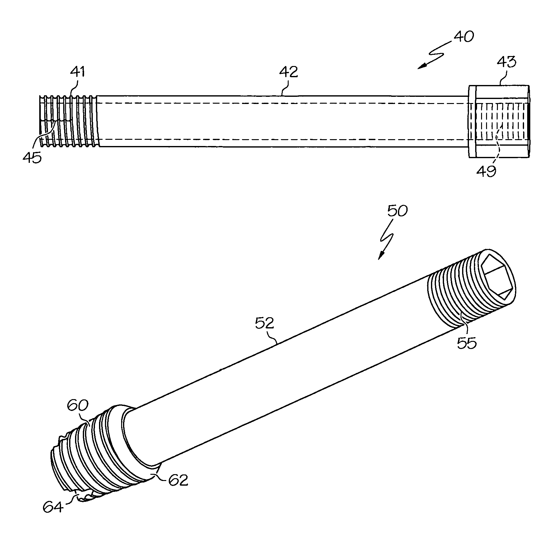
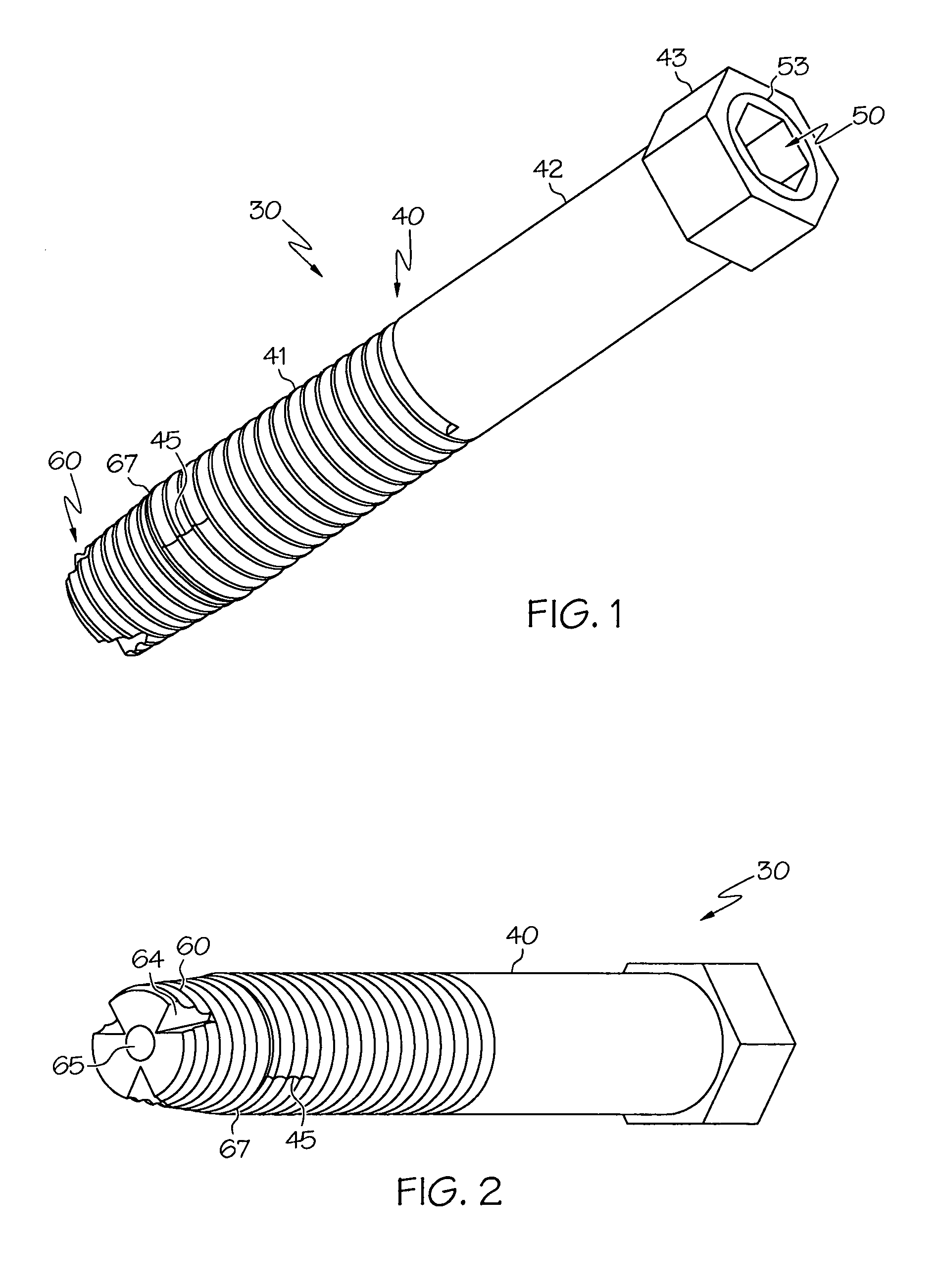
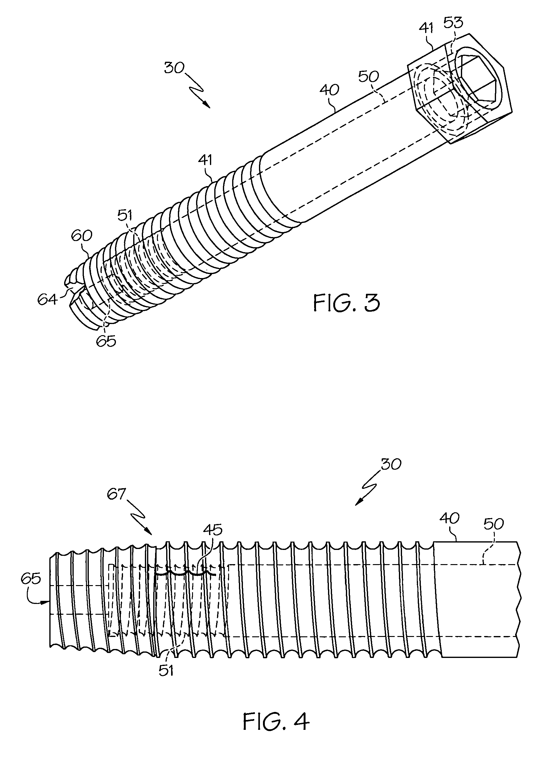
[0035]Referring generally to FIGS. 1, 2, 3, 4 and 11, there is illustrated a cannulated screw assembly 30. The cannulated screw assembly 30 is composed of an outer shank 40, an inner shank 50, and a tip 60. The tip 60 and a distal portion of the shaft 41 are threaded to such that the device may be inserted into and through two bones. It should be generally understood that while in the following description of a preferred embodiment the screw assembly 30 is described as inserted through two bones, the device may alternatively be inserted into and through two fragments of the same bone or an implantable device and a bone.

[0036]As shown in FIG. 5, the outer shank 40 comprises a head 43, an unthreaded portion 42 proximal to the head 43, and the threaded portion 41 at the distal end of the outer shank 40. The outer shank 40 further includes one or more slits 45 such that the tip 60 can move into the distal end of the outer shank 40 and cause outward deformation at the distal end. The out...

second embodiment

[0044]According to the above described second embodiment, rotation of the inner shank 50 and tip 60 with respect to the outer shank 40 causes the internal threading 49 at the proximal end of the outer shank 40 and the external threading 55 on the proximal end of the inner shank 50 to engage as shown in FIG. 16. The mating of the threads 49 and 55 creates a force that will cause the inner shank 50 and the tip 60 to be drawn up into the distal end of the outer shank 40.

[0045]The outer shank 40 of the second embodiment, like the outer shank 40 of the first embodiment, includes one or more slits 45 to facilitate deformation, and mutually chamfered tip and outer shank surfaces, 47 and 62, which meet at the interface 67 to further facilitate deformation. And similarly, the force associated with drawing the tip 60 up causes the distal end of the outer shank 40 to deform. The embodiment may further include the previously discussed collar 75 with the securing surface 76 for distributing forc...


PUM


Abstract

An assembly for the fixation of a spinal facet joint, including an outer shank, an inner shank and a tip, such that rotation of the inner shank with respect to the outer shank causes the tip to move into the outer shank. Movement of the tip causes deformation of the distal end of the outer shank such that the distal end of the outer shank is larger in diameter than the hole through which it was inserted, said deformation causing increased compression and reduced chance of device loosening.

Description

CROSS REFERENCE TO RELATED APPLICATIONS[0001]This application claims priority from the provisional patent application Ser. No. 61 / 070,795 filed Mar. 25, 2008 in the name of A. Joshua Appel and Marc C. Jacofsky entitled “Spinal Facet Fixation Device” incorporated herein by reference.FIELD OF THE INVENTION[0002]The present invention relates to a screw for the fixation of the facet joints of the human spine. More particularly, the invention relates to a device that is designed for use in the lower thoracic and lumbar spine, but may have wider application in general orthopedic uses including fracture fixation and implant fixation.BACKGROUND[0003]The facet joints, or zygapophyseal joints, of the spine are located at two symmetrical locations at the posterior of the vertebral column. Each facet joint consists of two overlapping bony protrusions, the superior articular process of one vertebrae and the inferior articular process of the neighboring vertebrae. FIG. 18 illustrates two vertebra...

Claims


Application Information

Patent Timeline
Patent Type & Authority Patents(United States)
IPC IPC(8): A61B17/68A61B17/86A61B17/70A61B17/88
CPCA61B17/686A61B17/7064A61B17/8685A61B17/8877A61B17/864A61B2017/564
Inventor JACOFSKY, MARC C.APPEL, A. JOSHUA
Owner THE CENT FOR ORTHOPEDIC RES & EDUCATION
Why Eureka
Try Eureka