Corrective fiber-optic microprobe for white light interferometric measurements

a technology of white light interferometry and fiber optics, applied in the field of optically corrective microprobe for white light interferometry, can solve the problems of inconvenient use, inconvenient use, inconvenient use, etc., and achieve the effect of convenient and convenient miniaturization, simple and constructed, and efficient and easy miniaturization arrangemen

Inactive Publication Date: 2015-07-07
GRINTECH
View PDF23 Cites 0 Cited by
  • Summary
  • Abstract
  • Description
  • Claims
  • Application Information

AI Technical Summary

Benefits of technology

[0009]It is crucial for a highly accurate, high-quality measurement, particularly in white light interferometry, that the measurement spot is generated as far as possible without aberrations and that wavelength-dependent optical path differences between the measurement light bundle and reference light bundle are minimized
[0010]Therefore, it is the object of the invention to find a novel possibility for white light interferometry which uses an expanded spectral range to allow the dispersion-induced dependency of optical path differences on the wavelength between measurement light bundle and reference light bundle to be compensated by an efficient and easily miniaturized arrangement even when optical elements whose dispersive materials bring about a wavelength dependency of the optical path differences are located between the optical surface which couples the reference light bundle out of the measurement light bundle and the measurement spot. An expanded object consists in that the solution can also be used to measure oblique and / or reflective object surfaces.
[0028]The invention makes it possible to provide a solution for white light interferometry which uses an expanded spectral range to allow the dispersion-induced dependency of path length differences on the wavelength between measurement light bundle and reference light bundle to be compensated by an efficient and easily miniaturized arrangement when optical elements, e.g., lenses, whose dispersive materials bring about a wavelength dependency of the optical path difference are located between the optical surface which couples out the reference light bundle and the measurement spot of the measurement light bundle. By generating the reference signal directly at the light output of the light-conducting fiber, the microprobe can be designed very simply and constructed so as to be mechanically stable over the long term and easy to miniaturize because complex mechanics are dispensed with. Further, it is no longer necessary to compensate for the dispersion in the interferometer in a probe-specific manner. Further, the invention is also suitable for interferometric measurements, particularly on oblique and / or reflective object surfaces using focusing optics with a higher numerical aperture (e.g., NA>0.55).

Problems solved by technology

A majority of the measuring systems based on this technique, however, involve large, relatively inflexible devices which are intended exclusively for carrying out a measurement task.
The reason for this consists primarily in the lack of availability of suitable, inexpensive sensor systems which are able to meet requirements with respect to miniaturization, accuracy, robustness and measuring speed.
However, a disadvantage in this solution is the virtually collimated parallel measurement light bundle which renders the microprobe undesirably sensitive to inclinations and irregularities on the object surface because the measurement signal fed back into the light-conducting fiber is severely weakened by a possible incline on the object surface.
However, the individually adapted optical elements and the very small concave end which is exactly adapted to the focal length of the microprobe require a high expenditure for production of the microprobe.
Another drawback of concave reference surfaces near the actual measurement spot, aside from the reduced divergence of the measurement light bundle, is that the concave surface must be positioned with micron to submicron accuracy with respect to the light emergence point of the single-mode (monomode) fiber of the microprobe because the reference light bundle reflected at the concave surface can only be efficiently fed back into the light-conducting fiber when there is a very good overlap of the virtual focus of the concave surface with the light-conducting fiber core, whose size is typically between 2 μm and 5 μm.
This requirement significantly complicates the mounting and alignment of all of the components relative to one another and assumes a long-term mechanical and climatic stability of the overall system that is difficult to achieve.
Therefore, it is hardly possible to miniaturize the microprobe while retaining robustness at the same time.

Method used


Image

  • Corrective fiber-optic microprobe for white light interferometric measurements
  • Corrective fiber-optic microprobe for white light interferometric measurements
  • Corrective fiber-optic microprobe for white light interferometric measurements

Examples


Embodiment Construction

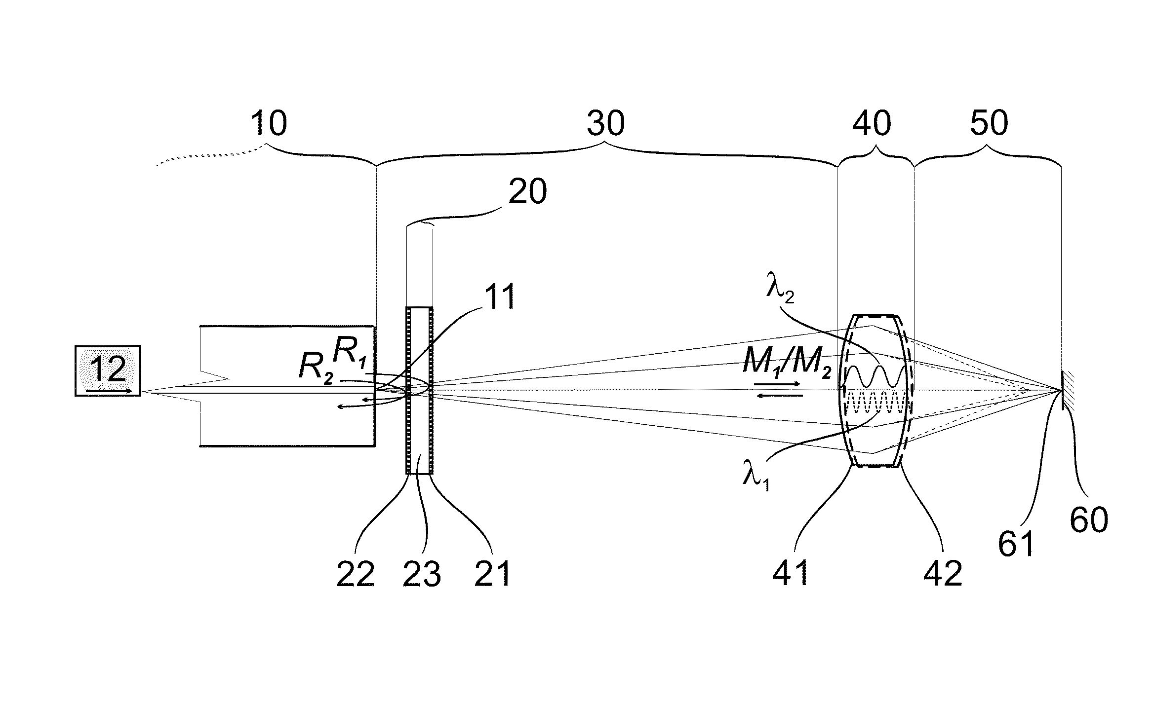
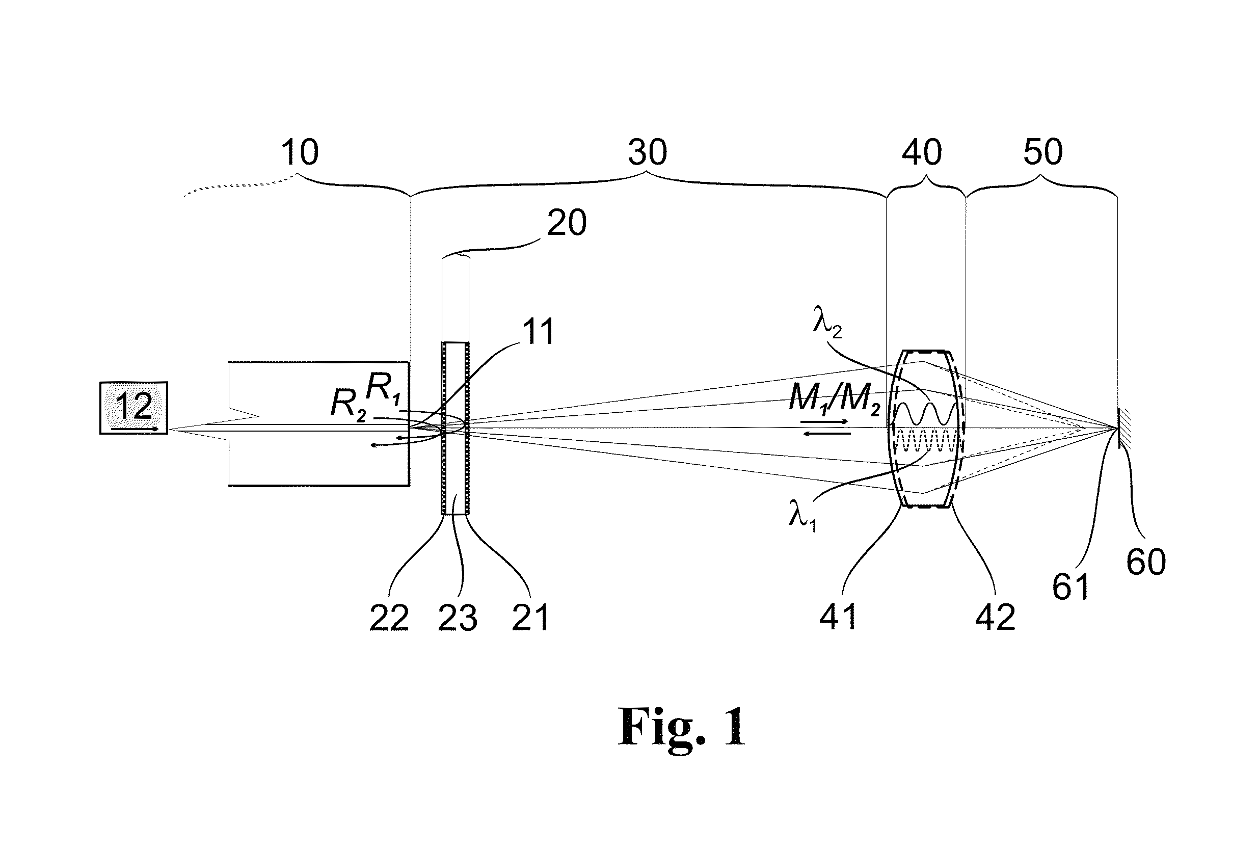
[0036]According to the optical construction shown in FIG. 1, the illustrated microprobe (shown more detailed as 80 in FIG. 5) includes a light-conducting fiber 10 for coupling in light. A reference beamsplitter 20 is arranged opposite a light output surface 11 of the light-conducting fiber 10. This reference beamsplitter 20 has at least two partially reflecting filters for coupling reference light bundles R1 and R2 out of at least two spectrally different measurement light bundles M1 and M2. The reference beamsplitter in FIG. 1 further has at least one partially reflecting interference filter 21 for a shorter-wavelength light spectrum around a center wavelength λ1 and a partially reflecting interference filter 22 for a longer-wavelength light spectrum around a center wavelength λ2. A spacer layer 23 which will be described more precisely in the following is arranged between the interference filters 21 and 22. Instead of the interference filters 21 and 22, other partially reflecting ...


PUM


Abstract

An optically corrective microprobe for white light interferometry is disclosed. In white light interferometry which uses different spectral ranges, the dispersion-induced dependency of optical path differences on the wavelength between measurement light bundle and reference light bundle is compensated by an efficient, easily miniaturized arrangement. A reference beamsplitter with partially reflecting filters in at least two different spectral ranges for generating at least two transmitted measurement light bundles and associated reflected reference light bundles of nonoverlapping spectral ranges is arranged between the light output surface of the light-conducting fiber and the focusing optics. An axial distance between two partially reflecting filters is adjusted in such a way that a spectrally induced optical path difference to which the respective measurement light bundles are subjected when passing through dispersive elements in the light path to the object surface and back is present to the same magnitude between the respective reference light bundles.

Description

RELATED APPLICATIONS[0001]This application claims priority to German Patent Application No. 10 2011 056 002.5, filed Dec. 2, 2011, which is incorporated herein by reference in its entirety.FIELD OF THE INVENTION[0002]The invention is directed to an optically corrective microprobe for white light interferometry, a method for producing the dispersion-correcting reference beamsplitter used for this purpose, and an arrangement for white light interferometry outfitted therewith.BACKGROUND OF THE INVENTION[0003]A large number of different evaluation methods exists in the field of optical metrology. Many of these employ interferometry with incoherent light or short coherence light in the visible and near infrared range. Because of the spectrum of light, the resolution of interferometric measurement methods is better than 1 μm in principle. As a result, these methods are particularly suitable for highly precise measurement of lengths, for example, in vibration analysis or surface inspection...

Claims


Application Information

Patent Timeline
Patent Type & Authority Patents(United States)
IPC IPC(8): G01B9/02G02B27/10G02B27/14G02B6/26G02B27/00G02B3/00G02B6/293
CPCG01B9/02049G01B9/02007G01B9/02057G01B9/0205G01B9/0209G01B9/02091G02B27/1006G02B27/141G01B9/02058G02B6/26G02B6/262G02B27/005G02B3/0087G02B6/29364G02B23/2423
Inventor MESSERSCHMIDT, BERNHARD
Owner GRINTECH
Why Eureka
Try Eureka