
Systems and methods for remotely measuring a liquid level using time-domain reflectometry (TDR)

a technology of time-domain reflectometry and liquid level measurement, which is applied in the direction of liquid/fluent solid measurement, instruments, machines/engines, etc., can solve the problems of remote measurement of water level, discrimination methods of time-domain reflectometry (tdr), and no one can design to remotely measure water level, etc., to achieve the effect of maintaining the impedance characteristics, reducing seismic forces, and propagating pulse tdr signals

Active Publication Date: 2015-07-07
GE HITACHI NUCLEAR ENERGY AMERICAS
View PDF13 Cites 18 Cited by
  • Summary
  • Abstract
  • Description
  • Claims
  • Application Information

AI Technical Summary

Benefits of technology

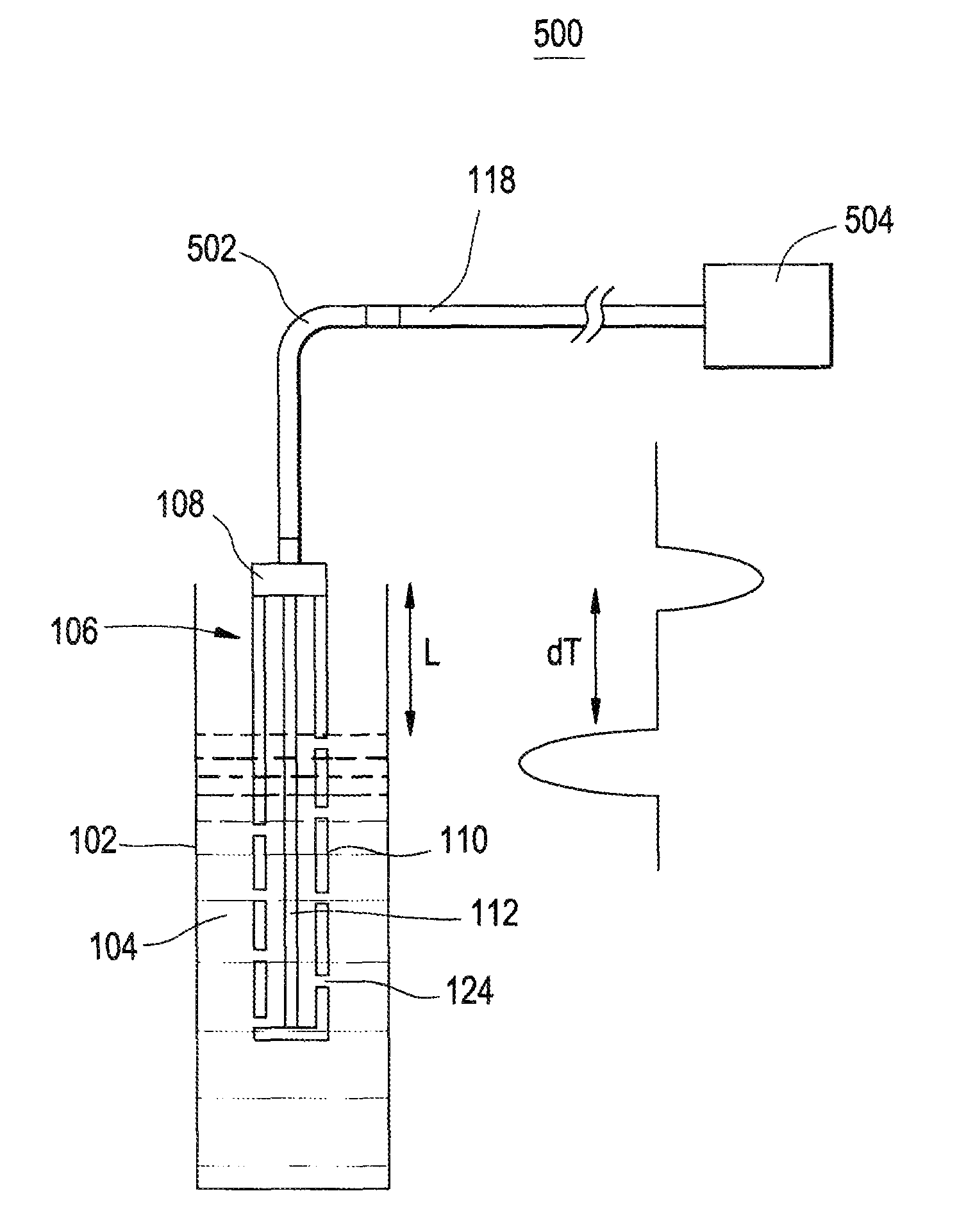
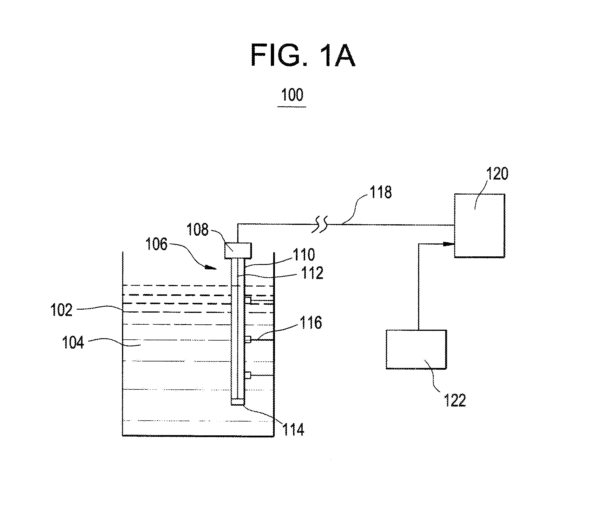
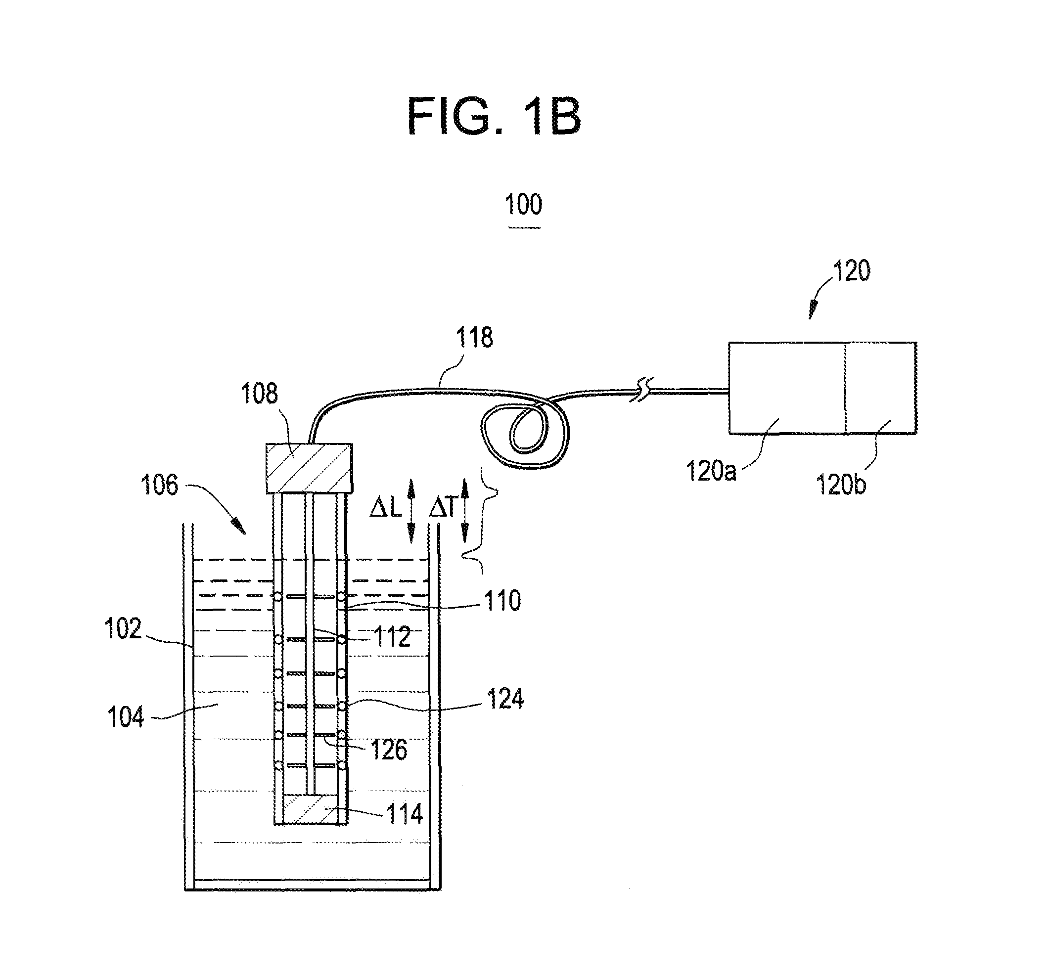
The patent describes a probe design for measuring water levels in a nuclear power plant. The probe is connected to a coaxial cable transmission line and is designed to have a constant impedance mismatch pulse. The probe is calibrated using a short calibration cable to prevent interference with the water level measurement. The probe is installed in a unique ball and socket design that allows for easy calibration and protection during seismic events. The design also allows for in-situ calibration by simply raising and lowering the probe vertically in the plant.

Problems solved by technology

Although there are time-domain reflectometry (TDR) based water level measurement systems, none are designed to remotely measure water levels (e.g., spent fuel pool (SFP) water levels) from relatively far distances by utilizing impulses and relatively highly specialized time-domain reflectometry (TDR) discrimination methods.
However, all such conventional techniques require electronics in the vicinity (i.e., relatively close proximity) of the spent fuel pool (SFP) and, thus, are not suitable for water level measurement in a hostile post-accident environment which could include high radiation, high temperatures, high seismic activity, fire, explosions, and falling debris.
Any small change in velocity could cause a significant error in water level because of the long length (e.g., 1000 ft.) of the cable.
This arrangement with the calibration cable effectively lengthens the distance from the top of the probe to the water level from the pulse timing point of view, since it allows the first reflection impedance mismatch Pulse #1 to occur at the interface between the calibration cable and the 1000 ft. cable and does not provide an impedance mismatch pulse at the probe top.
The use of a short calibration cable can also facilitate probe vertical movement and calibration, since the long coaxial cable transmission line may be fixed in a conduit and not able to move easily.

Method used


Image

  • Systems and methods for remotely measuring a liquid level using time-domain reflectometry (TDR)
  • Systems and methods for remotely measuring a liquid level using time-domain reflectometry (TDR)
  • Systems and methods for remotely measuring a liquid level using time-domain reflectometry (TDR)

Examples


Embodiment Construction

[0033]It should be understood that when an element or layer is referred to as being “on,”“connected to,”“coupled to,” or “covering” another element or layer, it may be directly on, connected to, coupled to, or covering the other element or layer or intervening elements or layers may be present. In contrast, when an element is referred to as being “directly on,”“directly connected to,” or “directly coupled to” another element or layer, there are no intervening elements or layers present. Like numbers refer to like elements throughout the specification. As used herein, the term “and / or” includes any and all combinations of one or more of the associated listed items.

[0034]It should be understood that, although the terms first, second, third, etc. may be used herein to describe various elements, components, regions, layers and / or sections, these elements, components, regions, layers, and / or sections should not be limited by these terms. These terms are only used to distinguish one eleme...


PUM


Abstract

A remote pulse TDR liquid level measurement system and method may include inserting a probe into a body of water. The probe has a probe / air interface, and the body of water includes an air / water interface. A narrow pulse is remotely transmitted to the probe via a coaxial cable. A first impedance mismatch is received from the probe / air interface in a form of a positive reflected pulse, and a second impedance mismatch is received from the air / water interface in a form of a negative reflected pulse. A time between the positive reflected pulse and the negative reflected pulse is calculated, and the time is converted to a distance, the distance being indicative of the water level.

Description

BACKGROUND[0001]1. Field[0002]The present disclosure relates to systems and methods for measuring a liquid level.[0003]2. Description of Related Art[0004]Conventionally, time-domain reflectometry (TDR) has been used to characterize and locate faults in metallic cables. Although there are time-domain reflectometry (TDR) based water level measurement systems, none are designed to remotely measure water levels (e.g., spent fuel pool (SFP) water levels) from relatively far distances by utilizing impulses and relatively highly specialized time-domain reflectometry (TDR) discrimination methods. For instance, one conventional time-domain reflectometry (TDR) system utilizes a step wave rather than impulse. Other conventional approaches include guided wave radar (GWR) techniques which use technology in this general category. However, all such conventional techniques require electronics in the vicinity (i.e., relatively close proximity) of the spent fuel pool (SFP) and, thus, are not suitable...

Claims


Application Information

Patent Timeline
Patent Type & Authority Patents(United States)
IPC IPC(8): G01R27/26G01R27/02G01F23/284G01R27/08
CPCG01F23/284G01R27/02G01R27/26G01R27/2605G01F23/26
Inventor DAYAL, YOGESHWARSPLICHAL, WILLIAM FRANCISSAWYER, STEVEN D.GARDNER, ERIC RANKINLENTNER, BRUCE J.EISERMANN, PHILIP O.
Owner GE HITACHI NUCLEAR ENERGY AMERICAS
Learn More