Magnetic memory using spin orbit interaction

a technology of magnetic memory and spin orbit, applied in the field of magnetic memory, can solve the problems of increasing electric power consumption, reducing cell occupancy ratio, and large required current for data wiring, and achieve the effect of small writing curren

Active Publication Date: 2015-07-14
RENESAS ELECTRONICS CORP
View PDF30 Cites 10 Cited by
  • Summary
  • Abstract
  • Description
  • Claims
  • Application Information

AI Technical Summary

Benefits of technology

[0024]According to the present invention, the magnetic memory in which the introduction of the domain wall is not required and the writing current is small can be provided.

Problems solved by technology

In the above-mentioned two-axis writing method (Patent literature 1) and the one-axis writing method (Patent literature 2) using the current induced magnetic field of the wiring line, there is a problem that the required current for data wiring is large.
The large writing current causes an increase of electric power consumption.
In addition, in the case of the two-axis writing method, it causes a decrease of a cell occupancy ratio due to an increase of an area of a cell selection transistor formed outside the cell array.
In this way, the large writing current causes degradation of device specifications.
On the other hand, in the magnetization inverting method (Patent literature 3) using the domain wall motion generated by the spin orbit interaction, there is a problem how the domain wall is introduced.

Method used


Image

  • Magnetic memory using spin orbit interaction
  • Magnetic memory using spin orbit interaction
  • Magnetic memory using spin orbit interaction

Examples


first embodiment

(First Embodiment)

[0100]A magnetic memory according to the first embodiment of the present invention will be described referring to the accompanying drawings.

[0101]In the present embodiment, in the two-axis writing method, a writing current is decreased by not using a current induced magnetic field using two wiring lines but using a current induced magnetic field using a single wiring line and using an effective magnetic field (a Rashba magnetic field: described later) based on a spin orbit interaction.

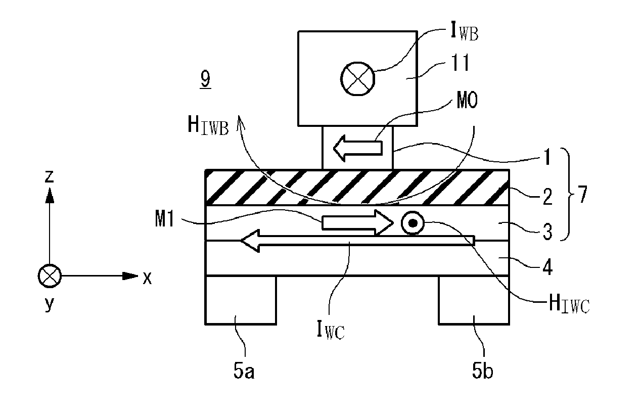
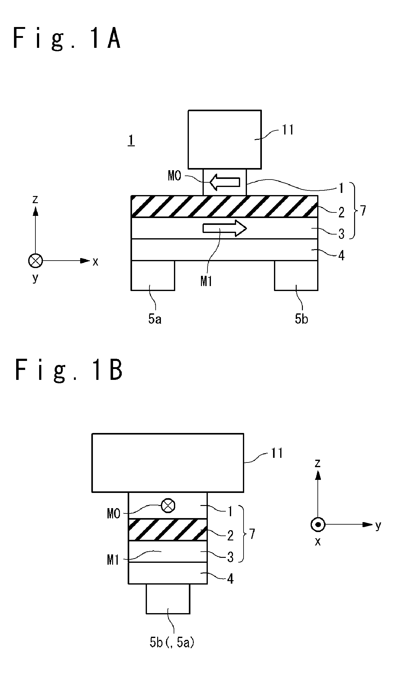
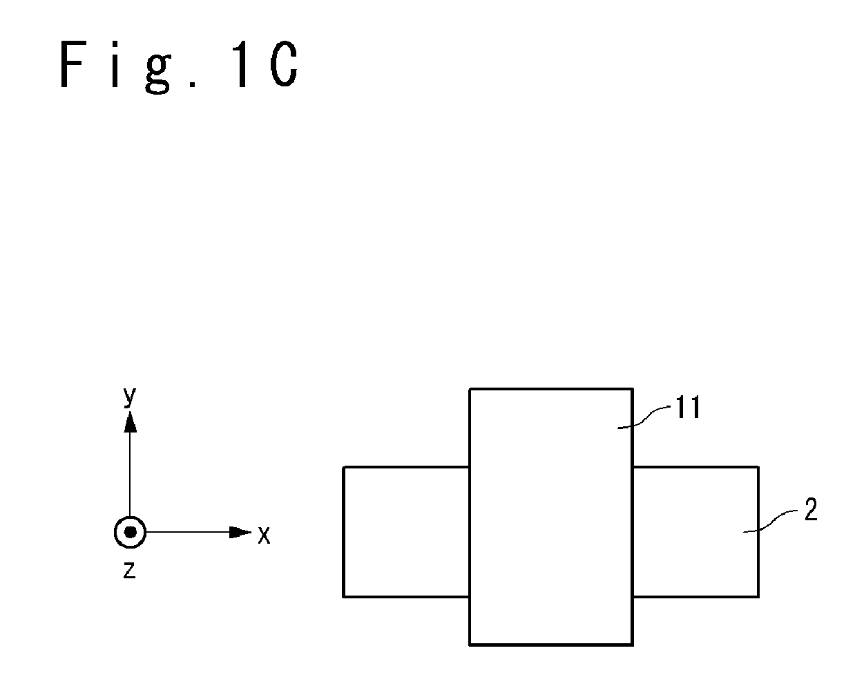
[0102]First, a configuration of a magnetic memory element of the magnetic memory according to the first embodiment of the present invention will be described. FIGS. 1A to 1C are an elevation view, a side view and a plane view showing the configuration of the magnetic memory element according to the first embodiment of the present invention. The magnetic memory element 9 includes a base layer 4, a magnetization free layer 3, a barrier layer 2, a magnetization reference layer 1, an uppe...

second embodiment

(Second Embodiment)

[0131]The magnetic memory according to the second embodiment of the present invention will be described referring to the attached drawings.

[0132]The present embodiment is different from the first embodiment in the point that the magnetization reference layer 1 and the magnetization free layer 3 have perpendicular magnetic anisotropy in the present invention while they have in-plane magnetic anisotropy in the first embodiment. The different point from the first embodiment will be mainly described below.

[0133]First, the magnetic memory element of the magnetic memory according to the second embodiment of the present invention will be described. FIGS. 8A to 8C are an elevation view, a side view and a plane view showing a configuration of the magnetic memory element according to the second embodiment of the present invention. The magnetic memory element 9a includes a base layer 4, a magnetization free layer 3, a barrier layer 2, a magnetization reference layer 1, an up...

third embodiment

(Third Embodiment)

[0146]The magnetic memory cell according to the third embodiment of the present invention will be described referring to the attached drawings.

[0147]In the present embodiment, in the one-axis writing method, a writing current is reduced by not using a current induced magnetic field by a single wiring line but mainly using an effective magnetic field (the Rashba magnetic field: described later) based on the spin orbit interaction. That is, the present embodiment is different from the first embodiment in the point that the current induced magnetic field generated by the current flowing in the upper electrode (the bit line) is not used for the data writing. The different point from the first embodiment will be mainly described below.

[0148]First, a configuration of the magnetic memory element of the magnetic memory according to the third embodiment of the present invention will be described. FIGS. 11A to 11C are an elevation view, a side view and a plane view showing t...


PUM


Abstract

A magnetic memory includes: a base layer; a magnetization free layer; a barrier layer; and a magnetization reference layer. The magnetization free layer, with which the base layer is covered, has invertible magnetization and is magnetized approximately uniformly. The barrier layer, with which the magnetization free layer is covered, is composed of material different from material of the base layer. The magnetization reference layer is arranged on the barrier layer and has a fixed magnetization. When the magnetization of the magnetization free layer is inverted, a first writing current is made to flow from one end to the other end of the magnetization free layer in an in-plane direction without through the magnetization reference layer.

Description

CROSS REFERNCE TO RELATED APPLICATION[0001]This is a National Stage of International Application No. PCT / JP2011 / 073647 filed Oct. 14, 2011, claiming priority based on Japanese Patent Application Nos. 2011-061930 filed Mar. 22, 2011, 2011-061939 filed Mar. 22, 2011 and 2011-076361 filed Mar. 30, 2011, the contents of all of which are incorporated herein by reference in their entirety.TECHNICAL FIELD[0002]The present invention relates to a magnetic memory and more particularly a magnetic memory using spin orbit interaction.BACKGROUND ART[0003]Research and development for a magnetic memory using a magnetic tunnel junction (a MTJ) has been actively performed. The magnetic memory has excellent characteristics such as high-speed writing, the infinite number of times of rewriting, and nonvolatility. Therefore, the magnetic memory is expected to be used not only for a monolithic memory but also for an embedded memory of a microcomputer and so on. As the magnetic memory, a magnetic random ac...

Claims


Application Information

Patent Timeline
Patent Type & Authority Patents(United States)
IPC IPC(8): G11C11/16H01L43/02H01L43/08H01L27/22
CPCG11C11/1675G11C11/161H01L27/228H01L43/02H01L43/08H10B61/22H10N50/10H10N50/80H10N50/85
Inventor SUZUKI, TETSUHIRO
Owner RENESAS ELECTRONICS CORP
Why Eureka
Try Eureka