
Mass analyser providing 3D electrostatic field region, mass spectrometer and methodology

a mass spectrometer and electrostatic field technology, applied in the direction of electric discharge tubes, particle separator tubes, particle separator tube details, etc., can solve the problem of complicated identification of masses from tof spectra in the presence of overtaking, the proposed planar system does not provide focusing in the drift direction, and all mt-tof mass spectrometers with closed orbits have a common drawback. , to achieve the effect of increasing the overall flight tim

Active Publication Date: 2015-07-14
SHIMADZU CORP
View PDF36 Cites 18 Cited by
  • Summary
  • Abstract
  • Description
  • Claims
  • Application Information

AI Technical Summary

Benefits of technology

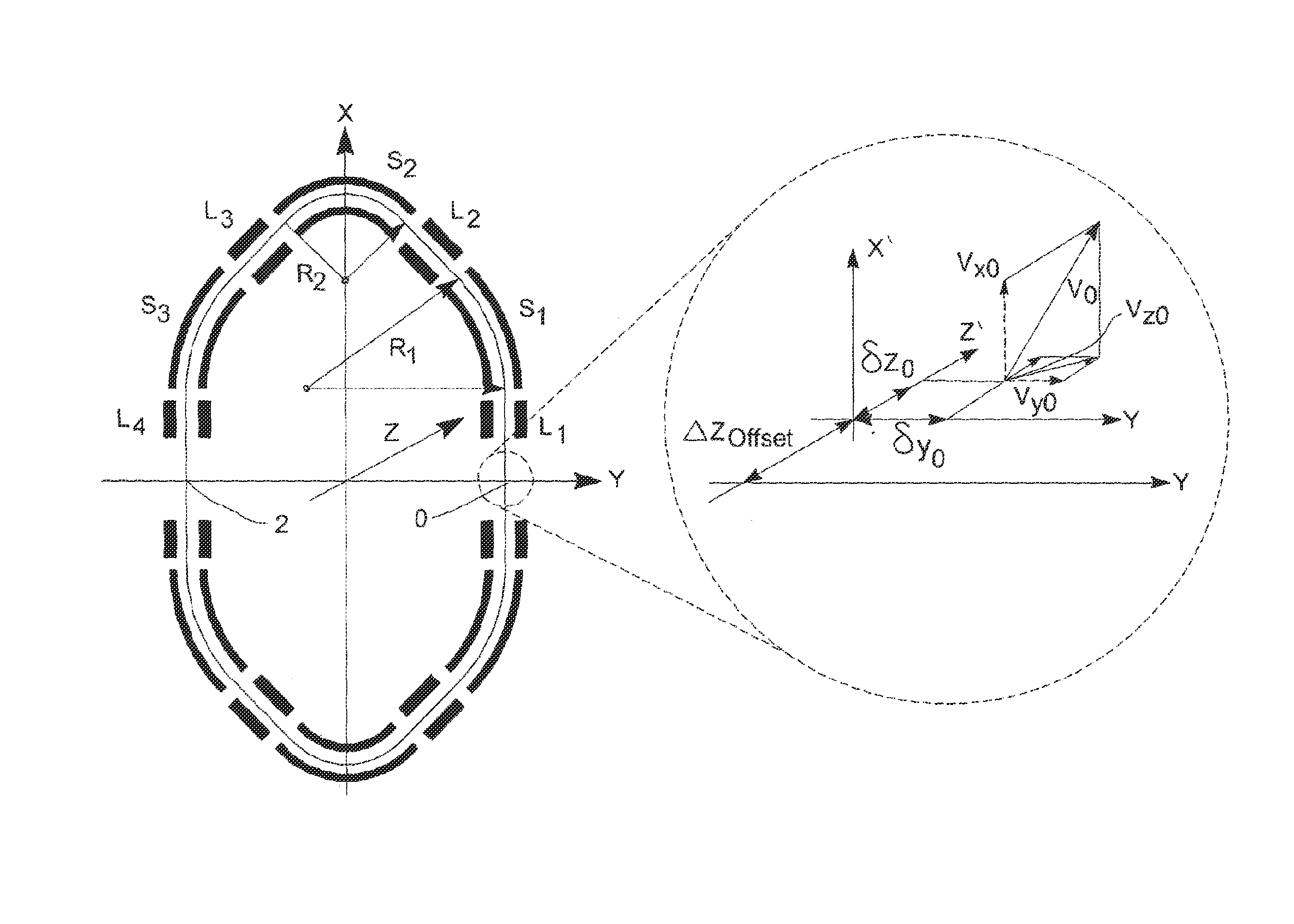
[0024]By configuring the mass analyser to guide ions having different initial coordinates and velocities along a single predetermined 3D reference trajectory that curves around the reference axis, the reference trajectory is able to be more compactly packed than with more conventional electrode arrangements (compare FIG. 5, Left with FIG. 5, Right), thereby allowing the mass analyser to use a smaller volume of evacuated space, thereby allowing the size and weight of the mass analyser to be reduced.
[0141]Preferably, the method may include configuring the set of electrodes to provide at least partial (e.g. partial spatial and / or energy, preferably both) isochronicity for ions travelling along different trajectories that curve around the reference axis. Isochronicity (preferably partial spatial and energy isochronicity) is highly preferable as it helps to achieve a good mass resolving power.

Problems solved by technology

The proposed planar systems did not provide focusing in the drift direction.
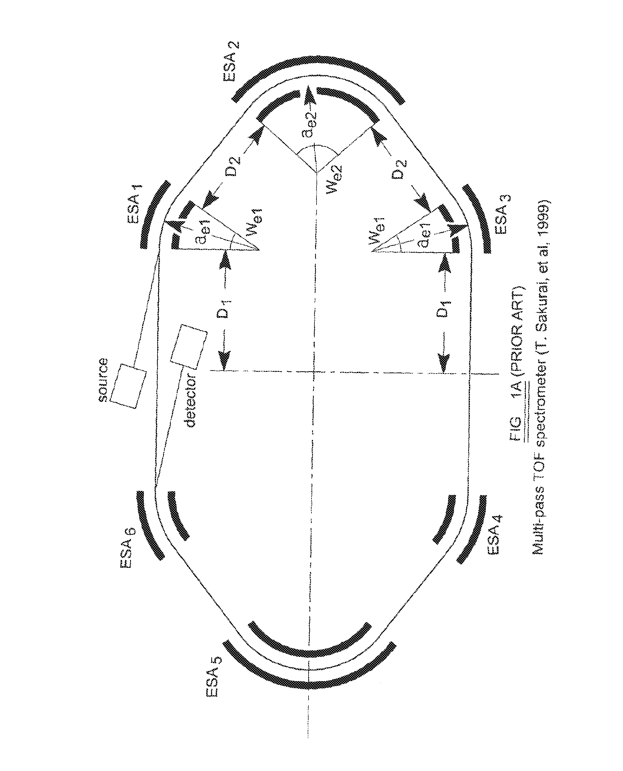
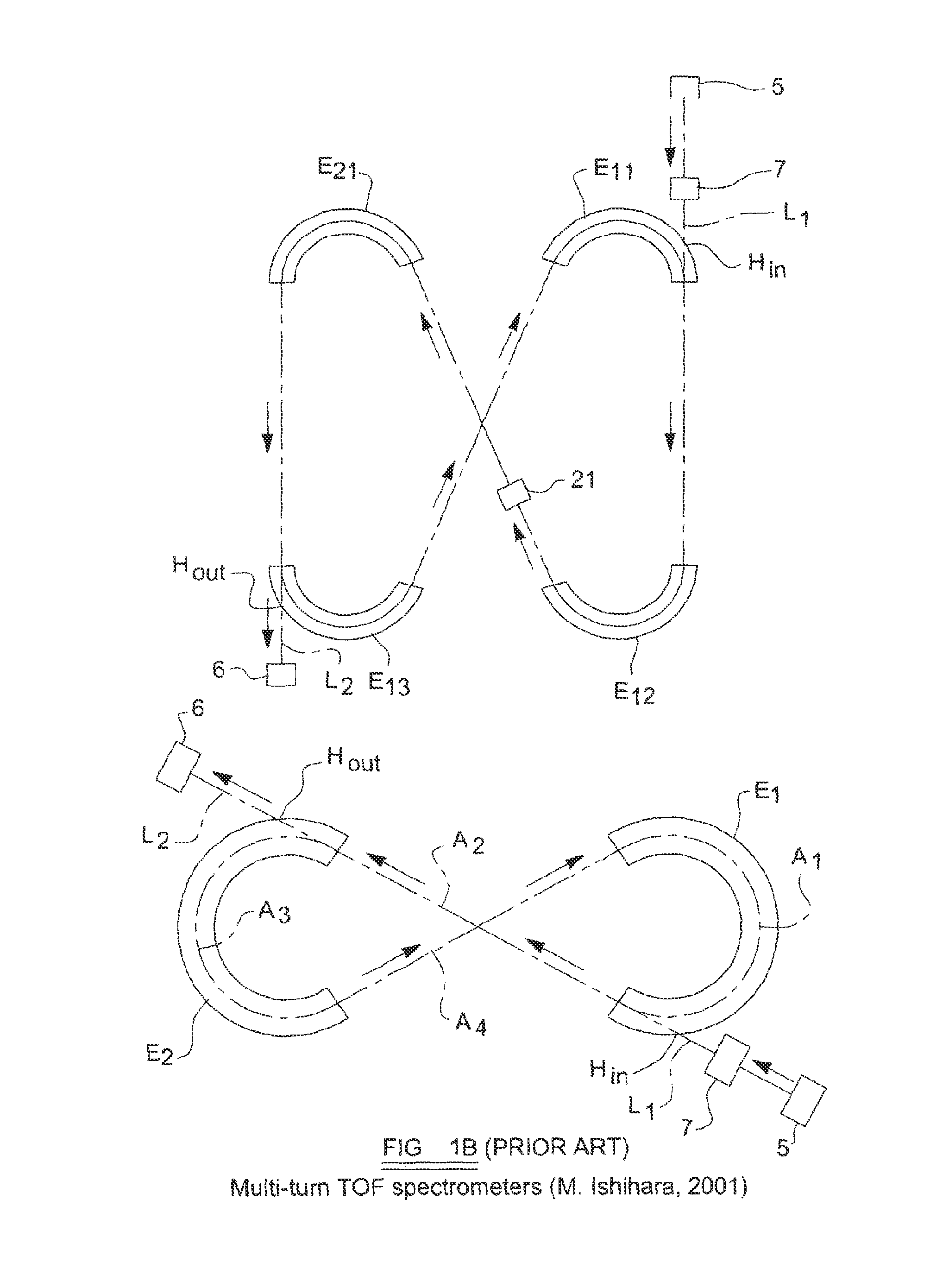
All MT-TOF mass spectrometers with closed orbits have a common drawback.
Unambiguous identification of masses from TOF spectra in the presence of overtaking is a complicate problem.
While the first approach results in very undesirable mass range limitation and the second approach has mass identification problems, the third approach of building an instrument with open trajectories does not have such problems.

Method used


Image

  • Mass analyser providing 3D electrostatic field region, mass spectrometer and methodology
  • Mass analyser providing 3D electrostatic field region, mass spectrometer and methodology
  • Mass analyser providing 3D electrostatic field region, mass spectrometer and methodology

Examples


Embodiment Construction

[0243]In general, the following discussion describes examples of our proposals that relate mainly to the field of the time-of-flight (TOF) mass spectrometry, and also to electrostatic trap mass spectrometers with image current detection and e.g. Fourier analysis.

[0244]FIG. 3A is a simplified diagram of a TOF mass spectrometer 100.

[0245]The TOF mass spectrometer 100 preferably includes an ion source 110 for producing ions having different initial coordinates and velocities. Preferably, the ion source 110 is configured to produce ions having different mass to charge ratios in short bunches, e.g. with each bunch of ions being produced in a short period of time, e.g. within a period of ˜1 nanosecond. Such bunches can be produced using a pulsed ion source, e.g. a MALDI ion source.

[0246]The TOF mass spectrometer 100 preferably includes an injection interface 120 produced by the ion source 110 into a mass analyser 130.

[0247]The mass analyser 130 is preferably configured as a TOF mass analy...


PUM


Abstract

A mass analyzer for use in a mass spectrometer. The mass analyzer has a set of electrodes including electrodes arranged to form at least one electrostatic sector, the set of electrodes being spatially arranged to be capable of providing an electrostatic field in a reference plane suitable for guiding ions along a closed orbit in the reference plane, wherein the set of electrodes extend along a drift path that is locally orthogonal to the reference plane and that curves around a reference axis so that, in use, the set of electrodes provide a 3D electrostatic field region. The mass analyzer is configured so that, in use, the 3D electrostatic field region provided by the set of electrodes guides ions having different initial coordinates and velocities along a single predetermined 3D reference trajectory that curves around the reference axis.

Description

[0001]This invention relates to a mass analyser for use in a mass spectrometer, to a mass spectrometer including such a mass analyser, and to associated methods.BACKGROUND[0002]Time-of-flight mass spectrometers (TOF MS) are widely used in modern mass spectrometry due to their high sensitivity, mass resolving power and mass accuracy. Achieving mass resolving power in the order of 100,000 or higher at ion charge throughput >109 ions per sec and infinite mass range are typical requirements to modern TOF MS instruments. Mass resolving power of early TOF MS instruments was generally of the order of only a few hundred due to short flight times and large time spreads caused by initial spatial and velocity spreads of ions. Impressive progress in TOF mass spectrometry over the last 50+ years has at least in part been due to development of pulsed ion sources capable of generating very short ion bunches with small transverse emittances, employing elongated ion trajectories (folded between i...

Claims


Application Information

Patent Timeline
Patent Type & Authority Patents(United States)
IPC IPC(8): H01J49/40H01J49/42H01J49/06H01J37/00
CPCH01J49/062H01J49/40H01J49/408H01J49/4245
Inventor SHCHEPUNOV, VYACHESLAVGILES, ROGER
Owner SHIMADZU CORP
Learn More