Method for separating a sample into density specific fractions

a density specific fraction and sample technology, applied in the field of centrifugation and vessels, can solve the problems of white cells negatively affecting the storage of platelets, distressed” platelets which partially disintegrate, and damage to the platelets by two spin centrifugation

Inactive Publication Date: 2015-08-11
MICROAIRE SURGICAL INSTR
View PDF3 Cites 5 Cited by
  • Summary
  • Abstract
  • Description
  • Claims
  • Application Information

AI Technical Summary

Benefits of technology

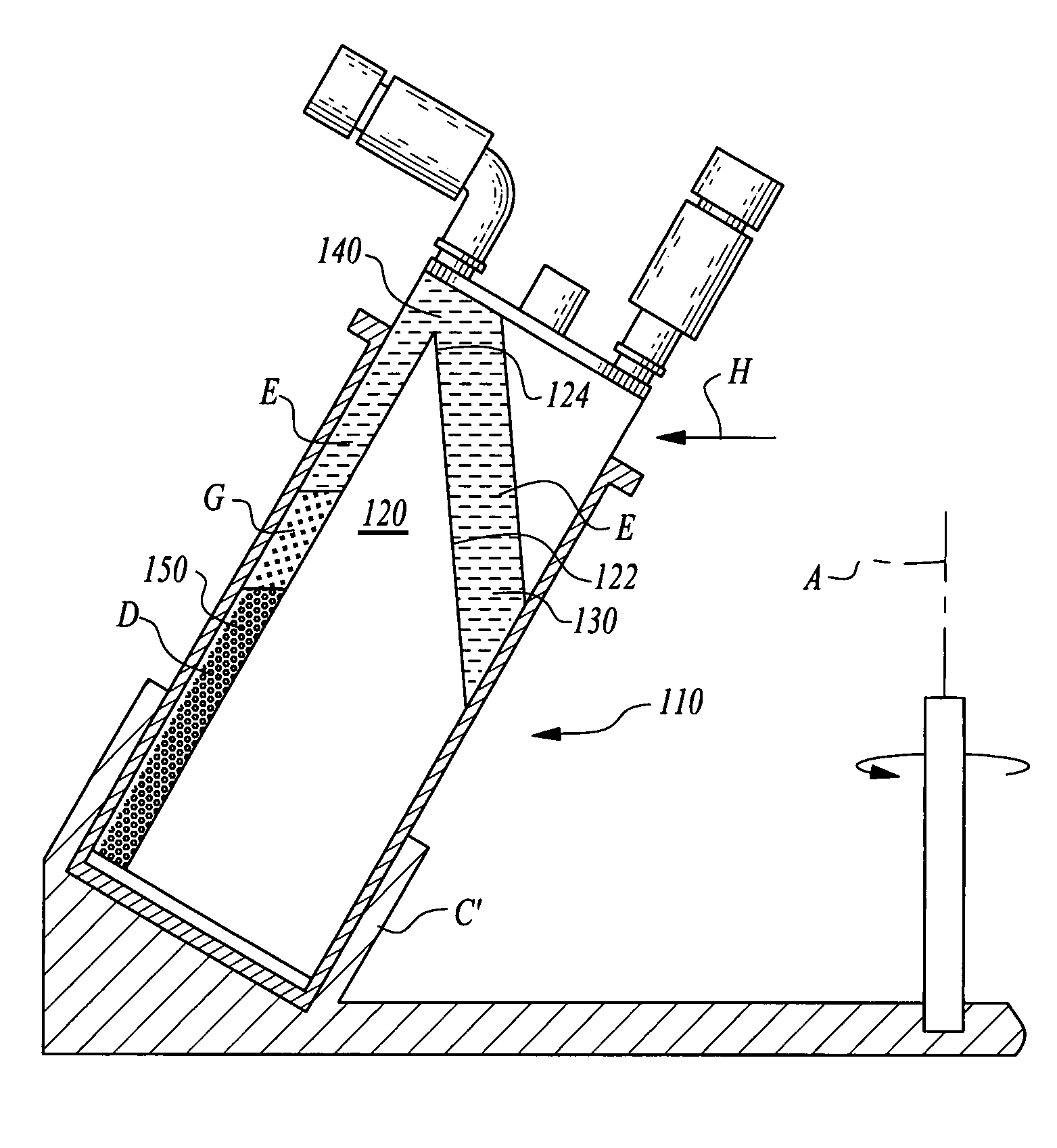
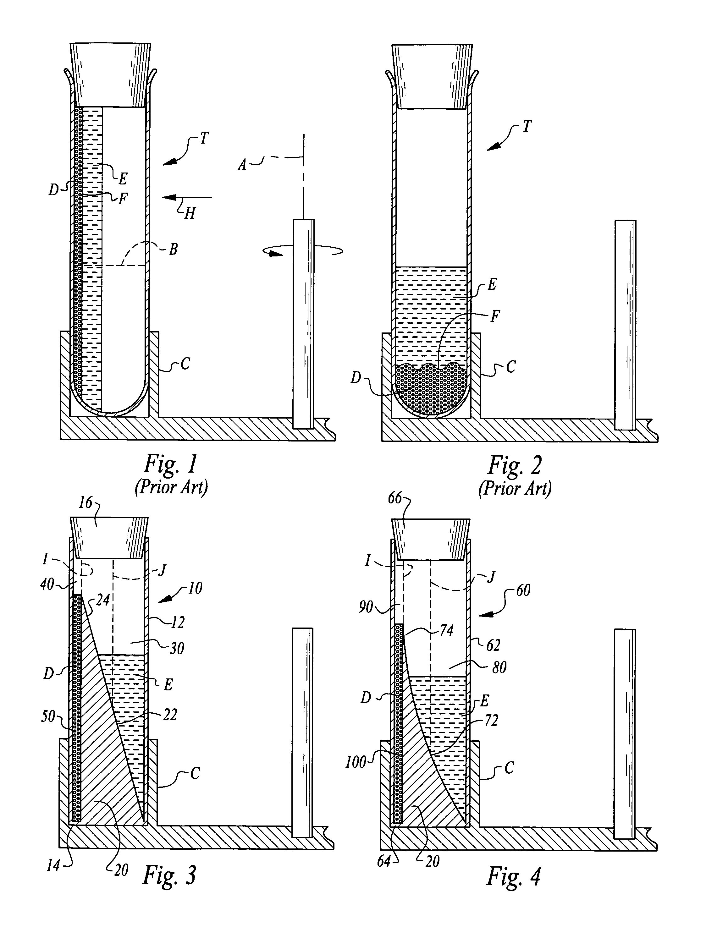
[0177]Furthermore, sample separation can be enhanced and accelerated by providing a face of the barrier closest to the spin axis with a taper. This taper is selected so that portions of the face closest to the lip are most distant from the spin axis with portions of the face most distant from the lip closest to the spin axis. This taper can be flat or curving, such as a concave curve, with different contours on the face adjusting the separation rate.
[0192]Another object of the present invention is to provide a method and apparatus for separating particulate containing fluids into at least two differing density fractions without the need for any moving parts, to enhance operational reliability.

Problems solved by technology

It is believed that two-spin centrifugation can damage the platelets by sedimenting the platelets against a solid, non-physiological surface.
The packing onto such a surface induces partial activation and may cause physiological damage, producing “distressed” platelets which partially disintegrate upon resuspension.
The white cells negatively affect platelet storage and may induce adverse effects after transfusion due to cytokine formation.
Therefore, much of the prior art focuses on leukoreduction of platelet concentrates because non-autologous leukocytes excite deleterious immune reactions.
Since the device was designed to be used in a normal medical setting with ample power, the permanent components, designed for long-term durability, safety and reliability, were relatively heavy, using conventional centrifuge motors and accessories.
The plasma fraction, being in an unconcentrated form, is not effective as a hemostat or tissue.
A major problem with that device was the inability to maintain a seal because it is costly to maintain the precise inner diameter of the test tube when mass produced.
This method of extraction necessarily is inefficient as a means of cell recovery as the intruding needle necessarily relocates the target cells above and below the through bore as it is inserted.
Hence, these known mechanical devices are generally capable of separating biological fluids into component parts or fractions; however, these devices are not very precise thereby resulting in inefficient separation of the biological fluid into component parts or fractions because of the substantial commingling of the separated fractions.
Additionally, these known mechanical devices fail to provide a simple or efficient method to extract a fraction other than the top fraction of the sample leading to low recoveries, especially of the clinically important buffy coat fraction.
Accordingly, this device relies on the imprecise longitudinal compression and decompression of the tube wall in order to control the flow path between fractions and fails to contain the separated fractions until after centrifugation stops and the tube wall returns to its original dimensions.
Hence, this recently patented device still fails to alleviate the problem of inefficient separation of the biological fluid into component parts or fractions and the commingling of the separated fractions.
This embodiment describes only one centrifugation spin, and fails to alleviate the problem of inefficient separation of the biological fluid into component parts or fractions and the commingling of the separated fractions.
Moreover, the device relies on the imprecise longitudinal compression and decompression of the tube wall in order to control the flow path between fractions and fails to contain the separated fractions until centrifugation stops and decompression of the tube wall is concluded.
Another problem associated with both embodiments of Leach, et al. is that the collection face, trough, or sump of the buoy must be shallow to be at a desired density level of the target buffy coat fraction and to preclude even further accumulation of reds cells with the target white cells and platelets to be extracted.
Thus, this shallow trough results in having the target white blood cells and platelets, come to rest on the entire large surface area of the first piston on which the white blood cells and platelets tend to stick, which reduces the efficiency of the final collection step.
A further problem associated with both embodiments of Leach, et al. is the time consuming and laborious process of fitting and interconnecting multiple parts to the device in order to perform the extraction process.
In general, current processes for separating and extracting fractions out of biological fluids require multiple steps that are both laborious and time consuming and that result in poor recoveries of the target white cells and platelets.
Process simplification also has a direct correlation to process reproducibility that is also a problem with the known prior art.
Hence, the known prior art is problematic in a number of areas which include a deficiency in the recovery efficiency of cells of interest (target cells), in the selectivity of separation for reducing contamination or non-target cells from the target cell population, and in the multiple step, laborious, and time consuming extraction process.
While this method has some significant advantage over the above-described purely manual methods, it has the drawback that the rather narrow passage between the compartments provides some resistance even during centrifugation which may prolong the operation.
Moreover, the method requires specially devised centrifugation vessels which renders it relatively costly.
Furthermore, since in accordance with that method the entire lowermost compartment must be filled with working fluid it is not possible to vary the amount of working fluid in a given centrifugation vessel.
The cell isolation process requires the manipulation of large volumes of lipid-laden cells, presenting potential risks to equipment and personnel.
Although it has been promoted for nearly three decades to separate adipose tissue components before grafting, there remain many controversies regarding the results obtained with centrifuged adipose tissue.
The authors state that an up-to-date, simple, but useful technique to evaluate the viability of fat grafts prior to transplant is lacking.

Method used


Image

  • Method for separating a sample into density specific fractions
  • Method for separating a sample into density specific fractions
  • Method for separating a sample into density specific fractions

Examples


Embodiment Construction

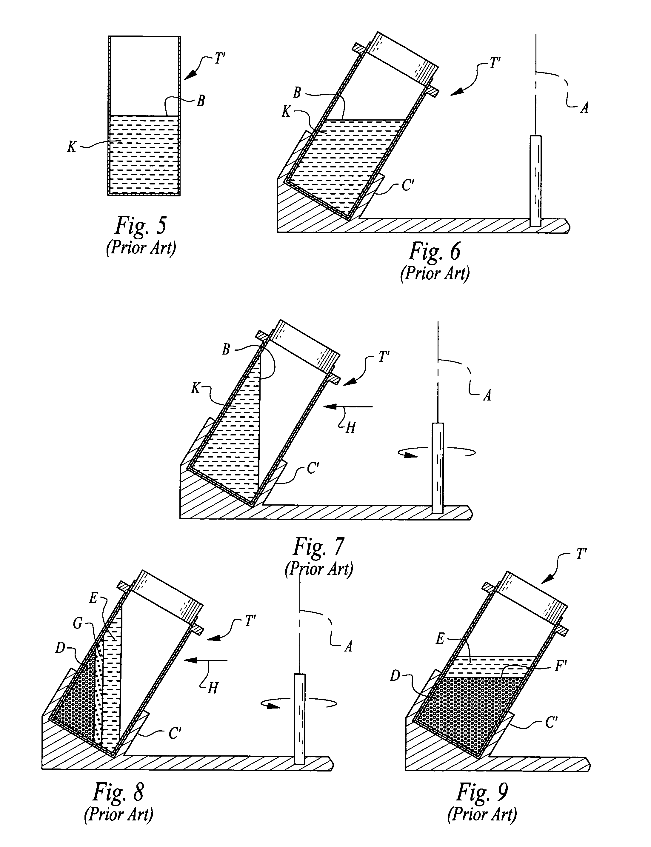
[0204]Referring to the drawings, wherein like reference numerals represent like parts throughout the various drawing figures, reference numeral 110 is directed to a preferred tube (FIGS. 10-12) for use in a centrifuge (FIGS. 15 and 16) to separate a sample K (FIGS. 13 and 14) into differing density constituents D, G, E (FIGS. 16-18) for separate collection and removal. By supplying a barrier such as a dam 120 (FIGS. 11 and 12) within a vessel, such as in the form of the tube 110, higher density fractions D of the sample K are caused to migrate through a spillway 140 from a reservoir 130 to a catch basin 150 for separate collection, facilitating later convenient and precise removal of various different fractions of the sample.

[0205]In essence, and with particular reference to FIGS. 10-12, basic details of the preferred tube 110 providing a preferred form of centrifugation vessel for biological sample separation, are described. The tube 110 is confined by an outer wall 112 and include...


PUM

PropertyMeasurementUnit
specific densityaaaaaaaaaa
volumeaaaaaaaaaa

Abstract

The centrifugation vessel includes an outer wall containing an interior space. A dam defines a barrier which divides the interior space into at least two regions including a catch basin defining a higher gee region and a reservoir defining a lower gee region. These regions are joined together over the dam. The dam includes a face which is preferably tapered to enable optimization of speed of separation of a sample placed within the vessel. The vessel is usable in a biological sample processing method by having the higher gee region of the vessel configured to have an elongate form and the volume optimized for collection of a higher density fraction of the sample. Supply and withdrawal tubes extend into the regions for reliable extraction and separate collection of differing density fractions after separation by centrifugation.

Description

CROSS-REFERENCE TO RELATED APPLICATIONS[0001]This application claims benefit under Title 35, United States Code §119(e) of U.S. Provisional Application No. 61 / 401,877 filed on Aug. 21, 2010.FIELD OF THE INVENTION[0002]The following invention relates to centrifuges and vessels therefore which are used in processes for separating a sample into fractions of different densities. More particularly, this invention relates to centrifuges and centrifuge operation methods which utilize sample containing vessel geometry to speed the sample separation process and maintain separation after centrifugation.BACKGROUND OF THE INVENTION[0003]Essentially a centrifuge is an apparatus that separates particles that are in a fluid. Centrifugation provides a means for achieving two goals through one approach: particles can be both concentrated and purified under centrifugal forces. Centrifugation of particles in a suspending medium causes the particles to sediment rapidly in the direction outward from the...

Claims


Application Information

Patent Timeline
Patent Type & Authority Patents(United States)
IPC IPC(8): B01L3/00G01N33/49A61M1/36
CPCB01L3/5021G01N33/491A61M1/3693B01L2300/0851B01L2400/0409B04B5/02B04B5/0414B04B1/00B01D21/262
Inventor CHAPMAN, JOHN R.SPARKS, RODNEYCOELHO, PHILIP H.
Owner MICROAIRE SURGICAL INSTR
Why Eureka
Try Eureka