Supercharge Your Innovation With Domain-Expert AI Agents!

Optimized frame system for a liquid crystal display device

a liquid crystal display and frame technology, applied in the field of optimized frame systems, can solve the problems of affecting the operation of light sources, the temperature of the liquid crystal display as a whole rises, and the components of the liquid crystal display normally possess poor thermal spreading properties

Inactive Publication Date: 2015-08-11
NEOGRAF SOLUTIONS LLC
View PDF65 Cites 6 Cited by
  • Summary
  • Abstract
  • Description
  • Claims
  • Application Information

AI Technical Summary

Benefits of technology

The objective of this patent is to create a frame system for display devices (such as liquid crystal displays) that is lightweight and structurally sound.

Problems solved by technology

In a liquid crystal display, the back or side lighting used to illuminate and enhance the viewing of the image display panel generates heat and thus constitutes a source of heat, which causes the temperature of the liquid crystal display as a whole to rise.
The heat generated in the light source is detrimental to the operation and viewing of a liquid crystal display.
Indeed, some of the electrical components in the display panel are themselves heat sources, which compounds the problem.
However, these other components of the liquid crystal display normally possess poor thermal spreading properties and are not normally designed to dissipate heat away from the light source, especially in directions parallel to the image display panel face.
The constant heat generation can accelerate thermal deterioration of the liquid crystal material from which the display is formed and shorten the useful lifespan of the liquid crystal display device.
Heat may also negatively affect the refresh rate of the screen.
The graphite heat spreaders of Tzeng are positioned between a heat generating electronic component and, advantageously, a heat sink, to increase the effective surface area of the heat generating component; the Tzeng patent does not address the specific thermal issues occasioned by display devices.
Heat passing from these heat sources contributes to uneven temperature distributions created on the panel unit itself, which adversely affects the image presented on the display panels as well as display panel reliability.
A support member such as this can add a significant amount of weight, and can be expensive and difficult to construct, due to physical requirements, the need for many threaded mounting features for the electronics, and the high cost of high thermal conductivity aluminum sheet.
This can mean more power being sent to the light sources, which increases the thermal load on the system and requires additional heat dissipation capabilities within the display units.
Active cooling solutions, such as fans and / or heat pipes, are undesirable due to unreliability, noise, and the fact that they contribute negatively to the cost and weight of the system.

Method used


Image

  • Optimized frame system for a liquid crystal display device
  • Optimized frame system for a liquid crystal display device
  • Optimized frame system for a liquid crystal display device

Examples


Embodiment Construction

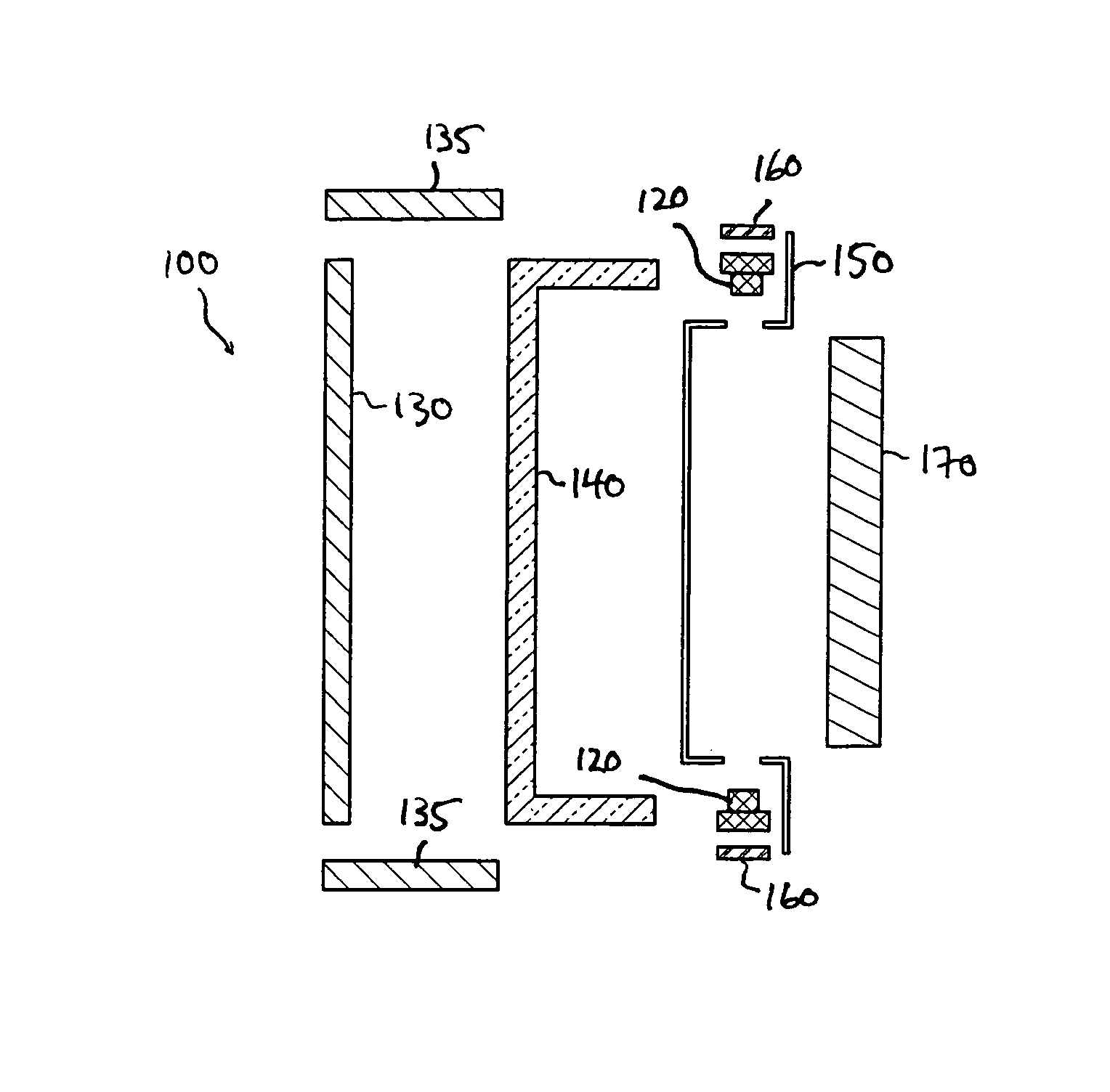
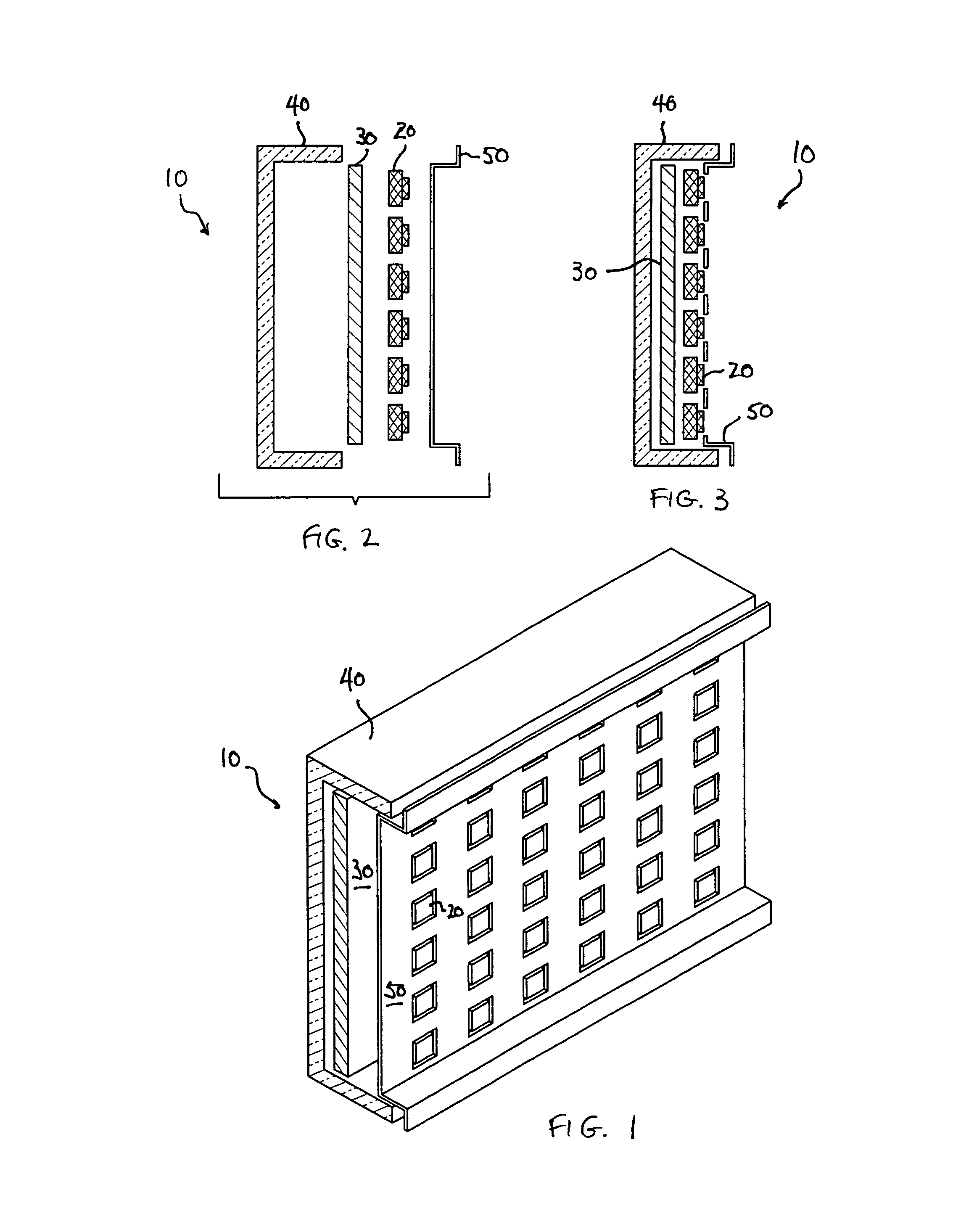
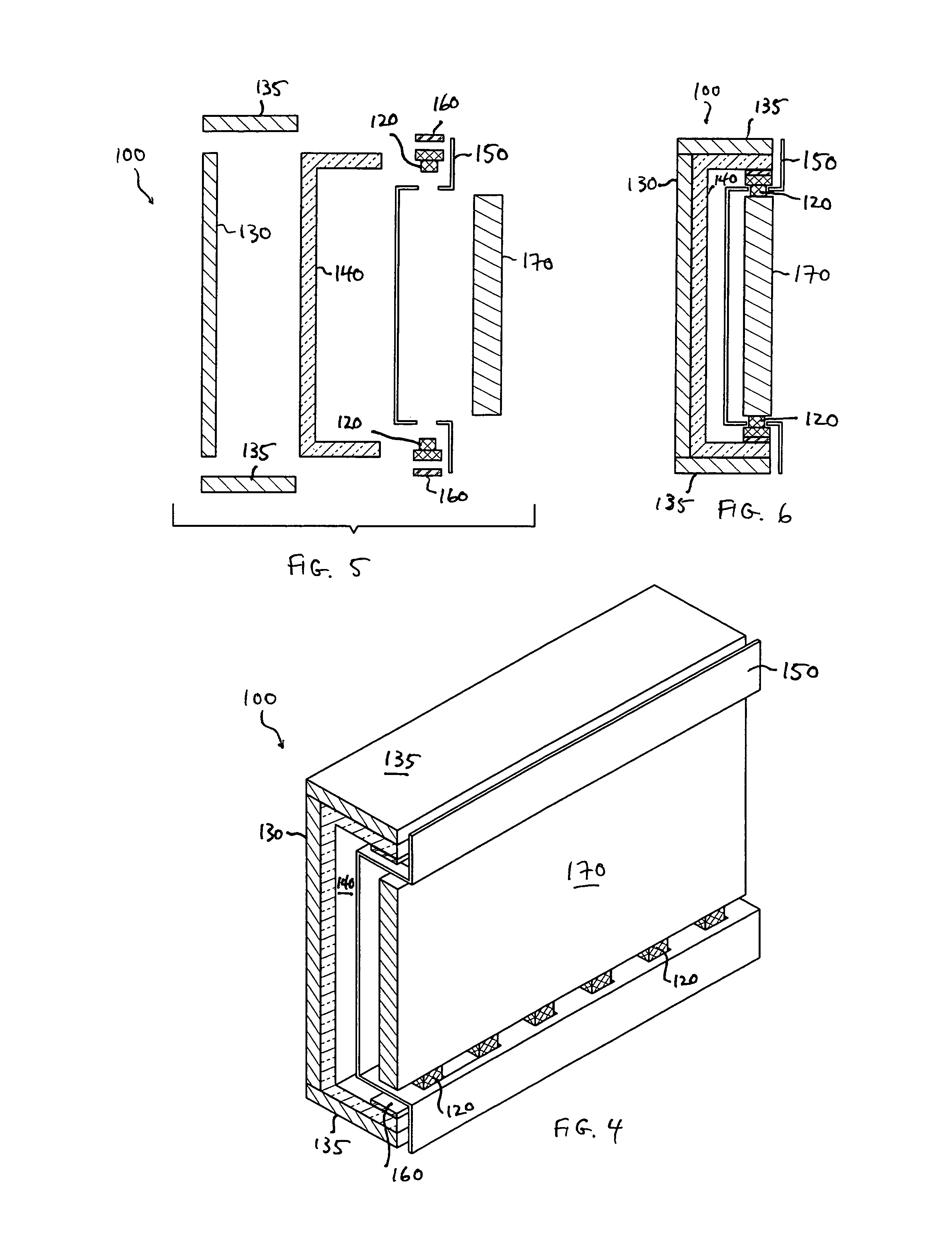
[0094]Referring generally now to FIGS. 1-3, a back-lit LCD image display device is shown and generally designated by the numeral 10. Device 10 comprises a series of light sources, such as LEDs 20 mounted so as to be directed to an image display panel (not shown). Device 10 further comprises heat dispersion material 30, formed of sheets of compressed particles of exfoliated graphite. Heat dispersion material 30 is in operative thermal contact with LEDs 20, such that heat generated by LEDs 20 is transferred to heat dispersion material 30. In addition, LCD device 10 can also comprises a support member b 40, such that the support factor of device 10 is less than about 375 mm-W / m° K. More preferably, support member 40 provides a support factor to device 10 of less than about 150 mm-W / m° K. As discussed above, however, in the most preferred embodiment of the present invention, the support factor of device 10 is 0 mm-W / m° K, meaning there is no support member 40 in LCD device 10. A reflect...


PUM

PropertyMeasurementUnit
densityaaaaaaaaaa
thickaaaaaaaaaa
thicknessaaaaaaaaaa

Abstract

An image display device comprising an image display panel, a frame system including a framework operatively engaging the image display panel and a plurality of electronic components operatively engaging the framework, heat dispersion material operatively engaging the framework and in operative thermal contact with the electronic components, where the frame system exhibits a support factor of less than about 375 mm-W / m° K.

Description

RELATED APPLICATION[0001]This application is a continuation-in-part of copending and commonly assigned U.S. patent application having Ser. No. 11 / 167,935, entitled “Optimized Frame System For A Display Device,” filed in the names of Shives et al. on Jun. 27, 2005, the disclosure of which is incorporated herein by reference.TECHNICAL FIELD[0002]The present invention relates to an optimized frame system used in conjunction with a heat spreader in a display device, such as a liquid crystal display (LCD), and the like, and the design and use of the frame system in view of the unique thermal issues occasioned by these devices.BACKGROUND OF THE ART[0003]A liquid crystal display, or LCD, is a display apparatus that utilizes an image display panel formed of two transparent sheets of polarizing material separated by a liquid containing rod-shaped crystals where the polarizing axes of the two sheets are aligned perpendicular to each other. The LCD is constructed to display an image by passing...

Claims


Application Information

Patent Timeline
Patent Type & Authority Patents(United States)
IPC IPC(8): G02F1/1333G02F1/1335H05K7/20
CPCG02F1/133385G02F1/133603H05K7/20963G02F2001/133628G02F1/133628G02F1/1333G02F1/133308G02F1/133382
Inventor SHIVES, GARY D.VARELA, WILLIAM
Owner NEOGRAF SOLUTIONS LLC
Features
  • R&D
  • Intellectual Property
  • Life Sciences
  • Materials
  • Tech Scout
  • Unparalleled Data Quality
  • Higher Quality Content
  • 60% Fewer Hallucinations
Learn More