Disposable apparatus for aligning and dispensing solder columns in an array

a technology of arrays and apparatuses, applied in the direction of soldering apparatus, auxiliary welding devices, semiconductor/solid-state device details, etc., can solve the problems of cte differences that are more problematic, and bga substrates that are often required, etc., to achieve a simple and elegant system. , the effect of increasing the degree of flexibility

Active Publication Date: 2015-08-18
THE TOPLINE CORP
View PDF15 Cites 10 Cited by
  • Summary
  • Abstract
  • Description
  • Claims
  • Application Information

AI Technical Summary

Benefits of technology

[0020]Accordingly, there is a need for a simpler and more elegant system and method for aligning and dispensing electrical interconnect members (e.g., solder columns) onto LGA, CGA or CCGA substrates without the user of vacuum or vibration.

Problems solved by technology

Ceramic substrates are often required in harsh environments or when excessive heat and power is present.
However, one problem with BGA devices is that a substantial difference in the coefficient of thermal expansion (CTE) can exist between BGA substrates and the PCB board.
The problem with CTE differences becomes more problematic when large size ceramic CBGA substrates are attached to PCB boards that are made of plastic glass-woven material such as FR-4, FR-5 or polyimide.
Over time, the electrical connection between the solder ball and metal pad will break between large size ceramic BGA substrates and a plastic glass-woven PCB due to CTE mismatching issues.
In the prior art, methods using tweezers to place solder columns by hand are time consuming and require an operator with dexterity to perform many repeated steps.
In addition, in the prior art, a person using hand placement methods may result in errors as the operator often fails to complete the specified pattern.

Method used


Image

  • Disposable apparatus for aligning and dispensing solder columns in an array
  • Disposable apparatus for aligning and dispensing solder columns in an array
  • Disposable apparatus for aligning and dispensing solder columns in an array

Examples


Embodiment Construction

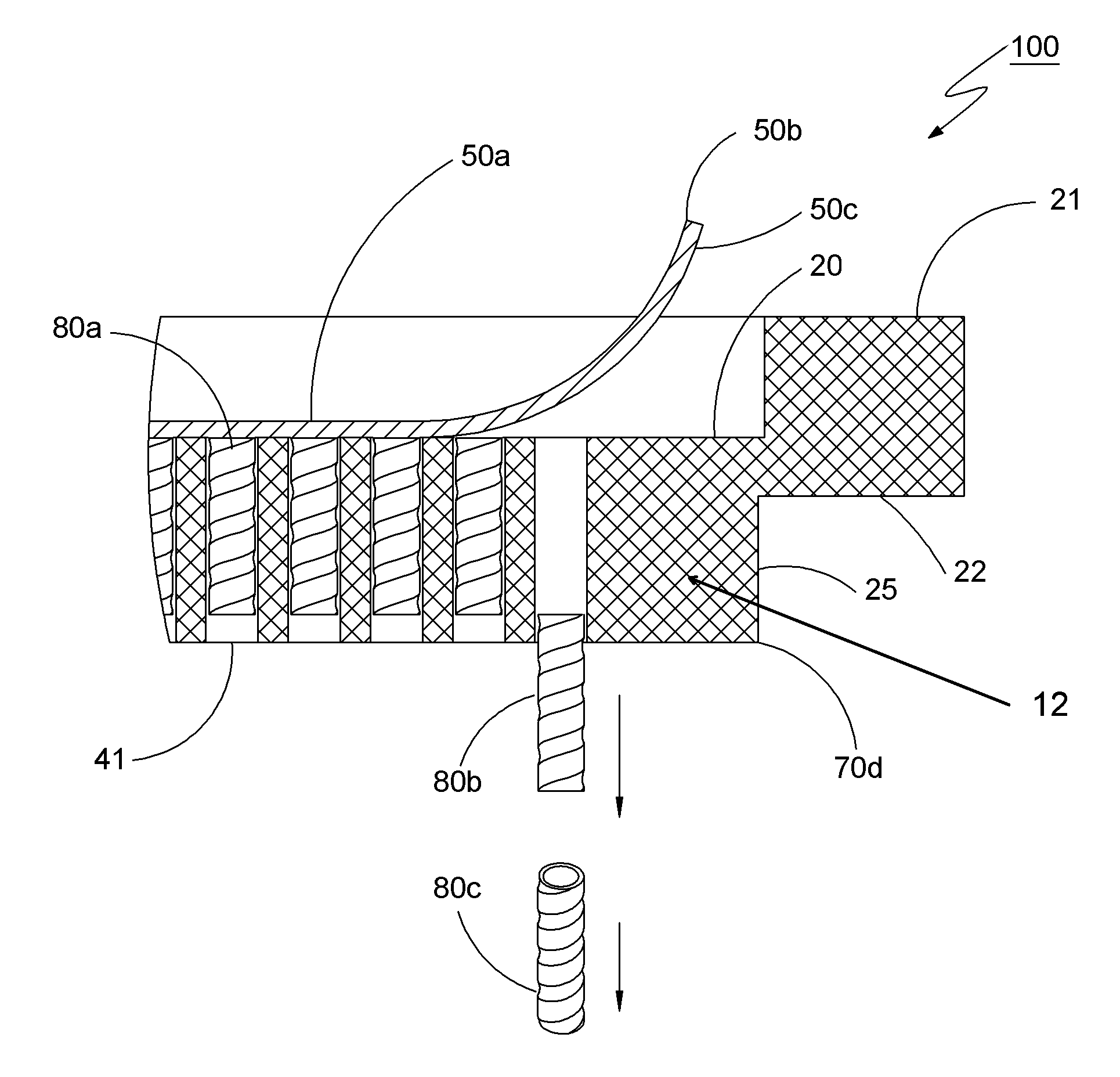
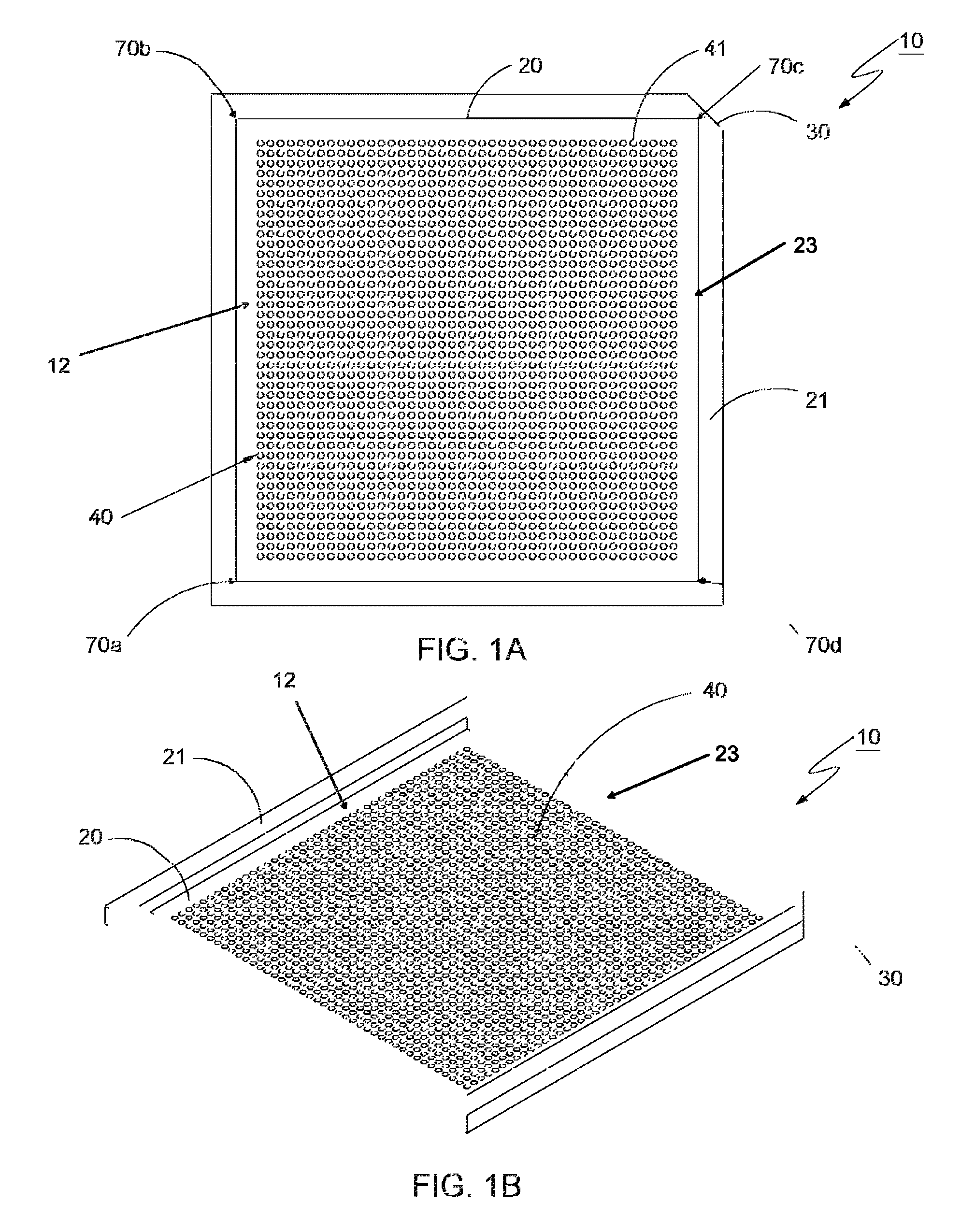
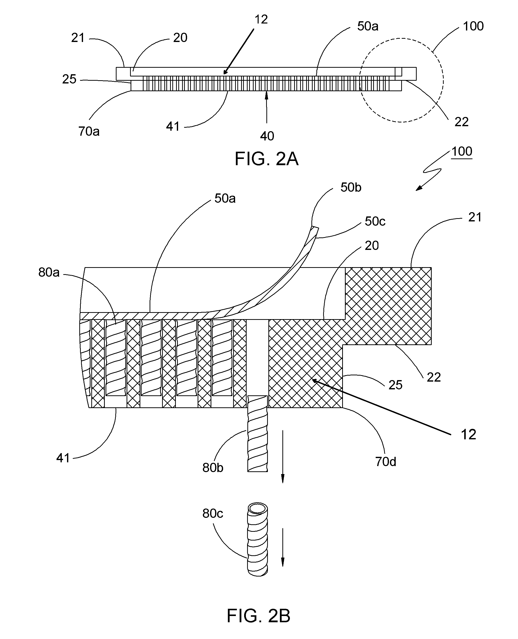
[0034]Referring first to FIGS. 1A and 1B, is an apparatus, shown for clarity without the adhesive layer (e.g., of sacrificial tacky tape) 50a in FIG. 2B and FIG. 3, generally designated at 10, that can hold, align and dispense one or more (e.g., a plurality of) electrical interconnect members 80 in any desired array pattern. The apparatus 10 can be shaped like a tray with a plurality (e.g., an array) of holes 40 that extend through a plate portion 12 of the tray 10. The one or more electrical interconnect members 80 can be solder columns, micro-coil springs, pins or other suitable generally cylindrical members that are releasably disposed in the holes 40 of the apparatus 10, as discussed further below.

[0035]FIGS. 2A, 2B and FIG. 3 show the adhesive layer 50a that is removably coupled to the apparatus 10. The bottom side 50c of the adhesive layer (e.g., sacrificial tape) 50a is advantageously sufficiently tacky to hold and releasably adhere to one end of the one or more (e.g., a plur...


PUM

PropertyMeasurementUnit
heightaaaaaaaaaa
diameteraaaaaaaaaa
diameteraaaaaaaaaa

Abstract

A disposable apparatus with a plurality of preloaded pins such as solder columns, micro-coil springs, or other cylindrically shaped metallic parts (solder columns, et al.) in an array pattern is provided for aligning and dispensing onto a column grid array (CGA) substrate. The apparatus is comprised of a carrier plate with a pattern of holes that is covered by a layer of sacrificial adhesive tape with sufficient tackiness to retain, position and hold an array of solder columns, et al. Alignment features on the bottom of the carrier plate plugs into a jig alignment fixture that precisely positions the solder columns, et al. over a CGA substrate. After peeling away the sacrificial adhesive tape from the apparatus, the payload of solder columns, et al. detaches and transfers by gravity onto a pattern of metal pads on the CGA substrate, without the use of vacuum or vibration.

Description

INCORPORATION BY REFERENCE TO ANY PRIORITY APPLICATIONS[0001]Any and all applications for which a foreign or domestic priority claim is identified in the Application Data Sheet as filed with the present application are hereby incorporated by reference under 37 CFR 1.57.[0002]The present application claims priority under 35 U.S.C. 119(e) to U.S. Provisional Patent Application No. 61 / 981,130 filed Apr. 17, 2014, the entire contents of which are hereby incorporated by reference and should be considered a part of this specificationBACKGROUND[0003]1. Field[0004]The present invention relates generally to column grid array (CGA) semiconductor packaging, and more particularly to an apparatus for aligning and dispensing a plurality of electrical interconnect members, such as pins, solder columns, micro-coil springs, or other cylindrically shaped metallic parts in an array pattern on a ceramic or plastic substrate.[0005]2. Description of the Related Art[0006]Typically, a layer of solder paste...

Claims


Application Information

Patent Timeline
Patent Type & Authority Patents(United States)
IPC IPC(8): B23K37/00B23K31/00B23K3/06
CPCH05K3/34H05K3/4015H05K2201/0311H01L21/4853H01L23/49811H01L2924/0002H01L2924/00
Inventor HART, MARTIN B.YOUNG, ROGER C.
Owner THE TOPLINE CORP
Why Eureka
Try Eureka