Sputtering method and apparatus
a technology of sputtering apparatus and sputtering method, which is applied in the direction of device material selection, vacuum evaporation coating, coating, etc., can solve the problems of adding to the complexity of the apparatus design or the way it is controlled, and the inability to adjust or control the substrate potential as appropriate, so as to achieve consistent suppression of pb loss
- Summary
- Abstract
- Description
- Claims
- Application Information
AI Technical Summary
Benefits of technology
Problems solved by technology
Method used
Image
Examples
example 1
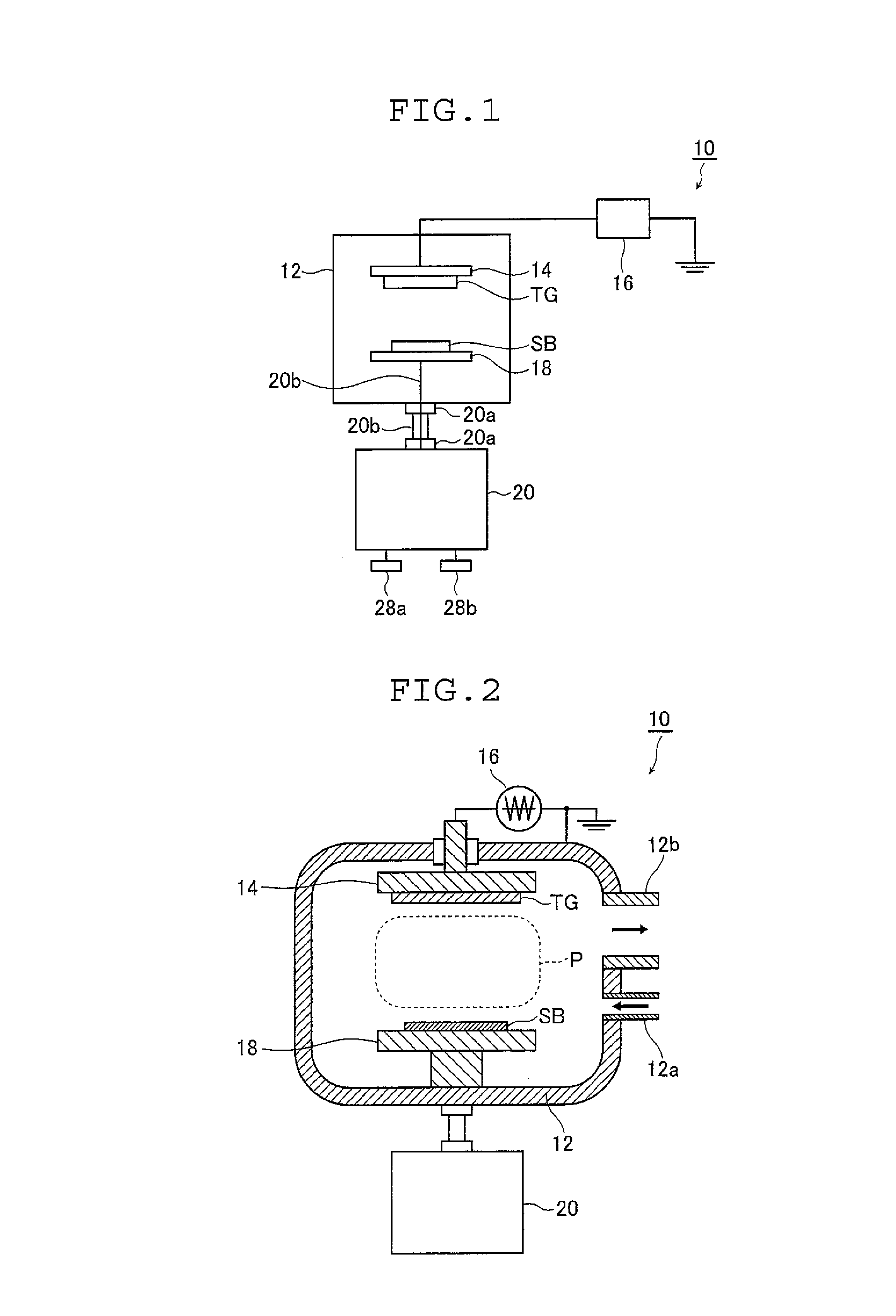
[0231]Model STV 4320 of Shinko Seiki Co., Ltd. was used as the sputtering apparatus 10 shown in FIGS. 1 and 2. In this sputtering apparatus 10, the substrate holder 18 was of such a design as to permit selection between the grounded state and a floating state. The RF power source 16 was capable of applying RF power of up to 1 kW.
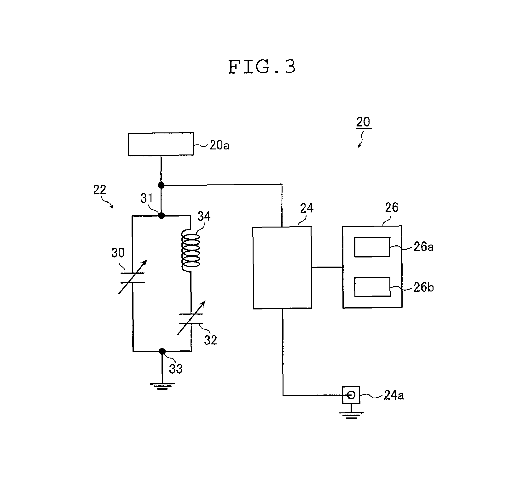
[0232]The sputtering apparatus 10 shown in FIGS. 1 and 2 used the impedance adjusting circuit 20 as shown in FIG. 3 and it was connected to the substrate holder 18.
[0233]A 4-inch size of sintered compact with the composition Pb1.3Zr0.52Ti0.48Ox was used as the target material TG. The substrate SB measured 5 cm by square and had Ti and Ir preliminarily formed in respective thicknesses of 10 nm and 150 nm on a Si wafer.
[0234]The target material TG and the substrate SB were spaced apart by 60 mm.
[0235]With the substrate temperature set at 525° C., a gas mixture of Ar and O2 (2.5%) was introduced to deposit a PZT film at 0.5 Pa.
[0236]With the substrate potential...
example 2
[0247]More than one batch of film deposition was performed for two cases, one where the substrate potential Vf was adjusted and the other where it was not. The results are shown in Table 3 below.
[0248]
TABLE 3VfVf(adjusted)(not adjusted)Batch 11010Batch 51011Batch 101013CleanedBatch 11010
[0249]As is clear from Table 3, the potential Vf of the substrate SB could be held constant in Example 2 by adjusting it but when it was not adjusted, the potential of the substrate SB changed gradually. In the absence of adjustment, an insulating film may have formed near the substrate holder 18 or on the side walls of the-vacuum vessel 12, causing the plasma state and, hence, the potential of the substrate SB to change. On the other hand, adjustment must have enabled film deposition to occur at a constant potential.
[0250]Therefore, by adjusting it, the substrate potential Vf can be held at a constant value or within a predetermined range to prevent a change in film quality, thus enabling piezoelect...
example 3
[0253]Two kinds of piezoelectric film, one being made of PZT and the other of Nb-doped PZT, were deposited from target materials Pb1.3Zr0.52T0.48O3 and Pb1.3Zr0.43Ti0.44Nb0.13O3 with the sputtering apparatus 10 shown in FIGS. 1 and 2 under such conditions that the degree of vacuum was 0.5 Pa and that the atmosphere was an Ar / O2 mixture (O2 volume fraction: 2.5%). In the following description, Nb-doped PZT is abbreviated as Nb-PZT.
[0254]A substrate with electrode, comprising a Si wafer having a 30-μm thick Ti adherent layer and a 150-nm thick lower Pt electrode superposed on it in that order, was provided as the substrate SB for film deposition. The distance between the substrate SB and the target material TG was set at 60 mm.
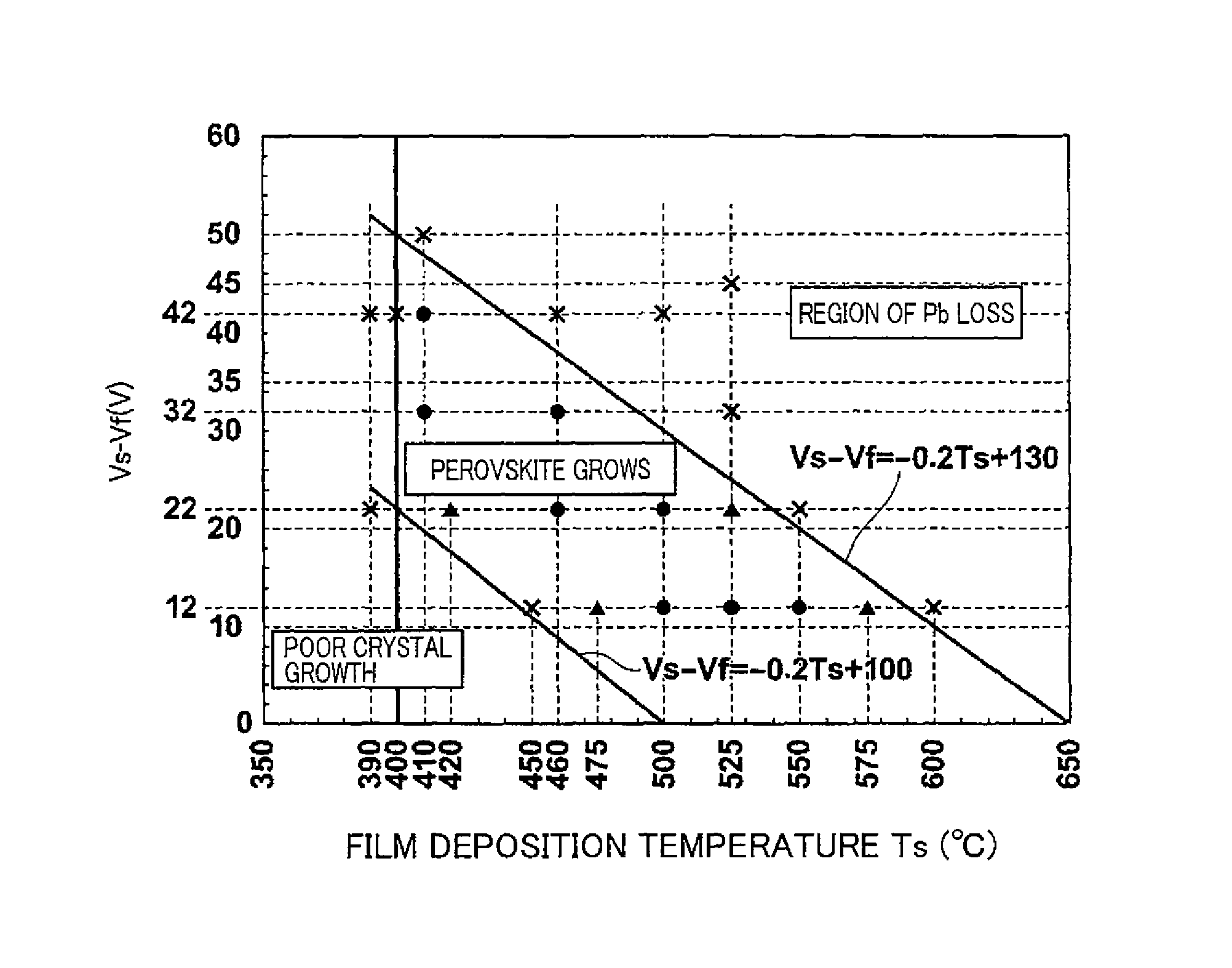
[0255]For film deposition, the potential Vf (V) of the substrate SB in a floating state was adjusted by varying the impedance of the substrate holder 18 with the impedance adjusting circuit 20. In the meantime, the plasma potential Vs was measured and the potent...
PUM
| Property | Measurement | Unit |
|---|---|---|
| distance | aaaaa | aaaaa |
| distance | aaaaa | aaaaa |
| temperature | aaaaa | aaaaa |
Abstract
Description
Claims
Application Information
 - R&D
- Intellectual Property
- Life Sciences
- Materials
- Tech Scout
- Unparalleled Data Quality
- Higher Quality Content
- 60% Fewer Hallucinations
Browse by: Latest US Patents, China's latest patents, Technical Efficacy Thesaurus, Application Domain, Technology Topic, Popular Technical Reports.
© 2025 PatSnap. All rights reserved.Legal|Privacy policy|Modern Slavery Act Transparency Statement|Sitemap|About US| Contact US: help@patsnap.com


