
Vehicle seat with lateral support element

a technology of lateral support and vehicle seat, which is applied in the direction of movable seats, child seats, chairs, etc., can solve the problems of pressure sores, the swivel range of the rotary adapter is limited, and the operating levers which are disposed further back and to the side cannot always be actuated comfortably

Active Publication Date: 2015-09-01
GRAMMER AG
View PDF58 Cites 4 Cited by
  • Summary
  • Abstract
  • Description
  • Claims
  • Application Information

AI Technical Summary

Benefits of technology

The patent describe a device that can provide added support to a vehicle driver's torso, reducing stress and increasing safety on the road. The device is designed to automatically adjust to the driver's body posture, providing a comfortable and efficient driving experience. The invention also relates to a method for reducing stress on the spinal column and promoting well-being for drivers. Overall, the technical effects of the patent are improved driver comfort, increased safety, and better driving performance.

Problems solved by technology

This can lead to pressure sores and thus to discomfort especially in the buttocks and thigh area of the driver of the vehicle.
Operating levers which are disposed further back and to the side still cannot always be actuated comfortably.
A further disadvantage is that the swivel range of the rotary adapter is limited by the fact that in spite of watching the working equipment behind the commercial vehicle, the vehicle must also be safely controlled by means of the pedals and the steering wheel.
In order to meet these requirements the driver of the vehicle must adopt an enforced posture which inevitably leads to twisting of the entire body.
Scientific studies show that such a twisted enforced posture in particular with vibrational stresses can lead to damage to the body structures, especially when the body is not sufficiently well supported.

Method used


Image

  • Vehicle seat with lateral support element
  • Vehicle seat with lateral support element
  • Vehicle seat with lateral support element

Examples


Embodiment Construction

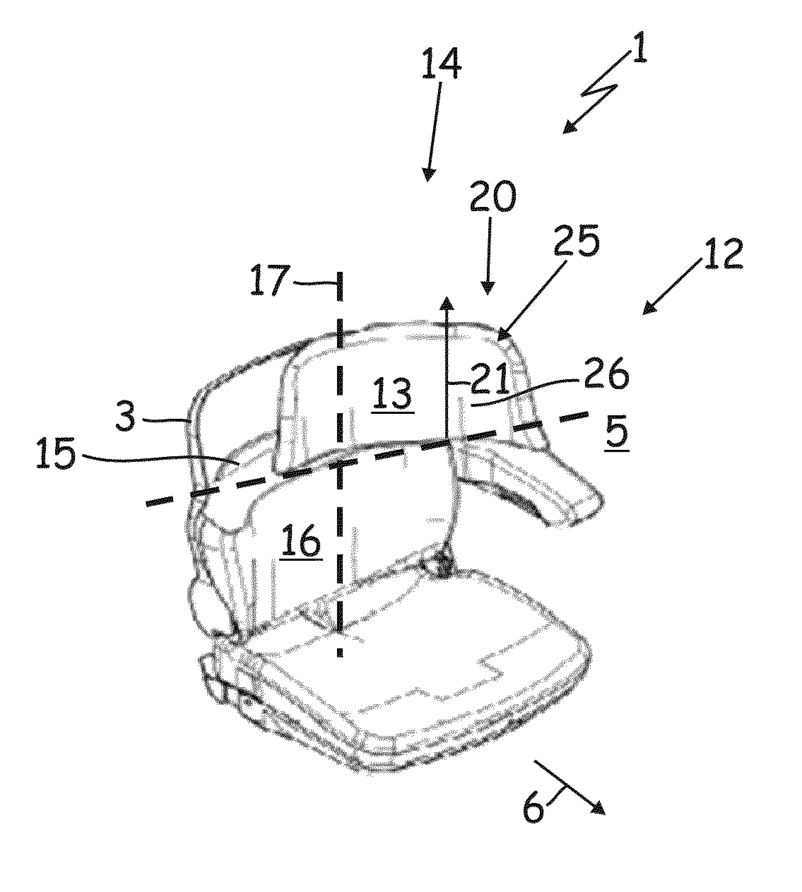
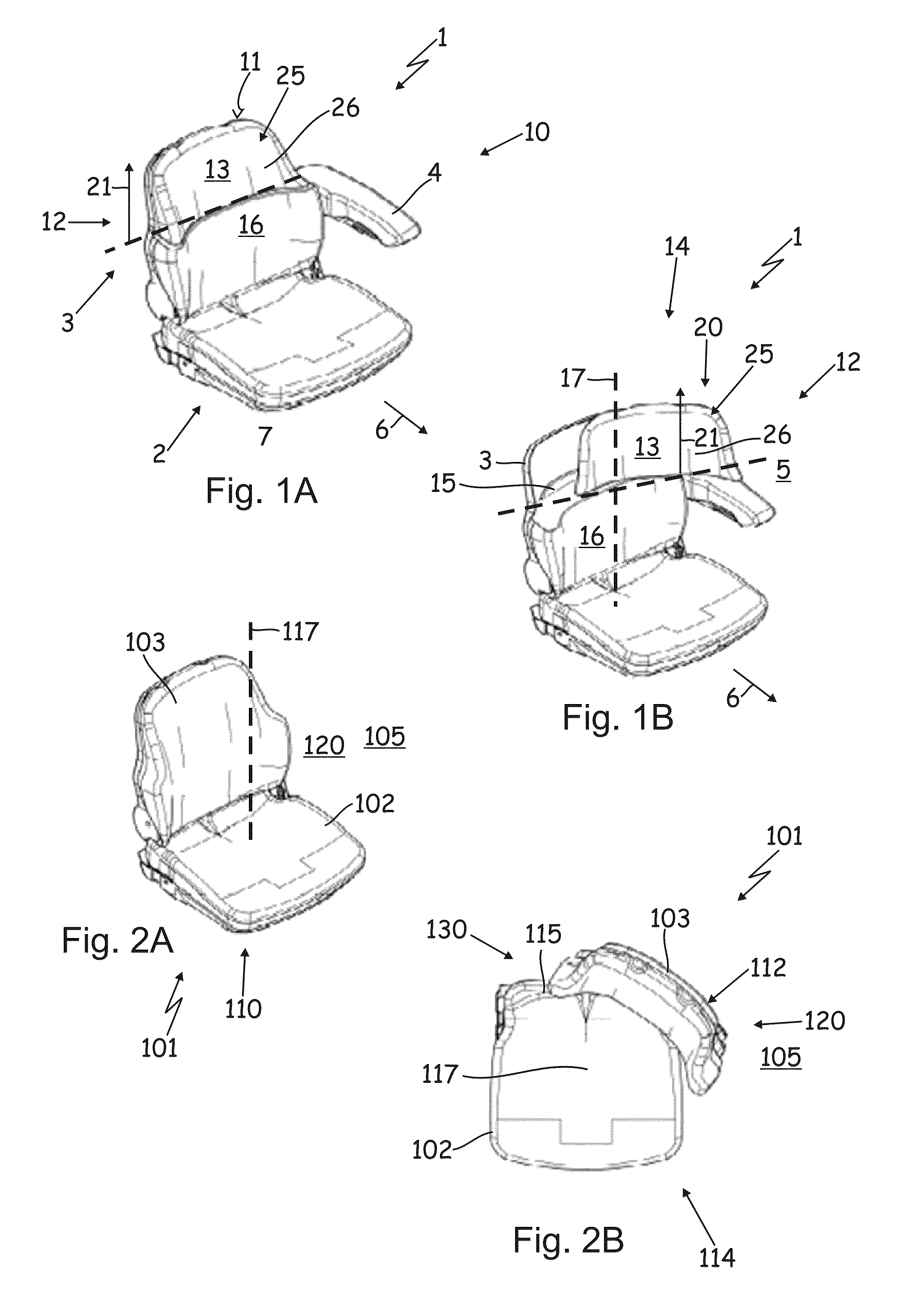
[0080]The vehicle seat 1 shown in FIGS. 1A and 1B is installed in an agricultural commercial vehicle not shown in greater detail here. The vehicle seat 1 primarily has a seat part 2, a seat back part 3 and an arm rest device 4 which is fastened on the left side 5 of the vehicle seat 1 when viewed in the forward travel direction 6 of the agricultural commercial vehicle. The vehicle seat 1 is fastened with the underside 7 of its seat part 2 by means of a bracket on a cab floor (not shown here) of the agricultural commercial vehicle. If appropriate, the bracket may comprise a spring device for spring mounting of the vehicle seat.

[0081]According to the illustration in FIG. 1A, the vehicle seat 1 is located in a normal support operating state 10, in which a driver of the vehicle (not shown here) is sitting on the vehicle seat 1 in a forward driving position and facing forwards. In this normal support operating state 10 the seat part 2, the seat back part 3 and the arm rest device 4 form ...


PUM


Abstract

The invention relates to a vehicle seat with a seat part and with a seat back part for supporting a driver of the vehicle in the sitting position on the vehicle seat, wherein the vehicle seat is characterized by an additional vehicle driver's torso support device which can be disposed outside the seat part and the seat back part and which can be temporarily disposed at least partially in an otherwise seat-free torso support region at the level of or above the upper third of the seat back part in front of the seat back part and laterally off-center on the seat back part, in order to provide support, laterally off-center of the seat back part, at least at the level of the shoulder or chest region of the driver who is sitting on the vehicle seat when he adopts a seated working posture oriented to the side or backwards, wherein the additional vehicle driver's torso support device is disposed so as to be movable by a moving device from a parked position into an additional torso support position in the otherwise seat-free torso support region.

Description

CROSS REFERENCE TO RELATED APPLICATIONS[0001]This application claims the benefit of German Application No. 10 2011 055 895.0, filed Nov. 30, 2011, the entire disclosure of which is incorporated herein by reference.BACKGROUND OF THE INVENTION[0002]The invention relates on the one hand to a vehicle seat with a seat part and with a seat back part for supporting a driver of the vehicle in his sitting position on the vehicle seat.[0003]On the other hand the invention relates to a commercial vehicle, in particular an agricultural commercial vehicle, with a vehicle seat.[0004]Furthermore, the invention relates to a method of supporting a vehicle occupant on a vehicle seat with a seat part and with a seat back part while the occupant temporarily adopts a driving / working position in which the occupant adopts or has adopted a sitting posture oriented sideways or backwards.[0005]Moreover, the invention relates to use of a seat back part of a vehicle seat. The invention also relates to use of a...

Claims


Application Information

Patent Timeline
IPC IPC(8): A47C1/10A47C7/36A61G15/00B60R22/28B60N2/38B60N2/22B60N2/28B60N2/46B60N2/64B60N2/48B60N2/75B60N2/90
CPCB60N2/38B60N2/2222B60N2/2851B60N2/4606B60N2/4855B60N2/64B60N2/4808B60N2/14B60N2002/022B60N2/753B60N2/856
Inventor BUEHLMEYER, KATJAHALLER, ERWINKOLB, JENSUEBELACKER, ROLANDERKER, CHRISTIAN
Owner GRAMMER AG
Learn More