Battery warm-up apparatus of hybrid electric vehicle

a hybrid electric vehicle and battery warm-up technology, applied in the direction of engine-driven generator propulsion, automatic control system, process and machine control, etc., can solve the problem of inability to carry out active warm-up control, and achieve the effect of increasing the charge of the battery per unit time, increasing the amount of battery discharge per unit time, and warming up the battery more quickly

Inactive Publication Date: 2015-09-01
DAIMLER AG
View PDF17 Cites 8 Cited by
  • Summary
  • Abstract
  • Description
  • Claims
  • Application Information

AI Technical Summary

Benefits of technology

[0012]Exemplary embodiments of the present invention solve the above described problems, and provide a battery warm-up apparatus of a hybrid electric vehicle that can properly carry out battery warm-up control when the vehicle is at a standstill, and therefore, reliably increase the temperature of a battery to recover charge-discharge performance.
[0020]The wet clutch device is switched to engaged state through action of hydraulic pressure, but when the vehicle is at a standstill, hydraulic pressure does not have to act because the wet clutch device is held unengaged. This can prevent degradation in fuel economy caused by an increase in load on the engine, which drives a hydraulic pump. On the other hand, when the temperature of the battery is low, the battery warm-up control unit switches the wet clutch device into engaged state to connect the engine and the electric motor together, thus enabling battery warm-up control for warming up the battery to be properly executed by varying the driving force of the electric motor alternately to the positive side and the negative side so as to repeatedly charge and discharge the battery. As a result, the charge-discharge performance of the battery can be reliably recovered.
[0022]Thus, because only the second clutch required for warm-up control of the battery is engaged and the first clutch is held unengaged, load on the engine for driving the hydraulic pump and consequent fuel consumption by the engine can be minimized.
[0023]In the battery warm-up apparatus, when the remaining capacity of the battery is less than the lower limit determination value, the battery warm-up control unit may prohibit the driving force of the electric motor from varying to the positive side and continuously control the driving force of the electric motor to the negative side to charge the battery.
[0024]Therefore, even when the remaining capacity of the battery is small, the battery can be charged to be warmed up. Moreover, when driving of the vehicle is to be restarted, the battery has a sufficient remaining capacity, and thus it is possible to respond accurately to requests in travel using the electric motor.
[0026]In this case, the battery warm-up control unit may set the target rotation speed at which the driving force of the electric motor is varied to the negative side so as to be equal to a rotation speed higher than the idle speed, whereby the amount of electrical power generated by the electric motor acting as a generator is increased, so that the amount of charge of the battery per unit time increases. On the other hand, the battery warm-up control unit may set the target rotating speed at which the driving force of the electric motor is varied to the positive side so as to be equal to a rotation speed lower than the idle speed, whereby the amount of electrical power consumed by the electric motor acting as a motor is increased, so that the amount of discharge of the battery per unit time increases. Thus, by increasing at least one of the amount of charge and the amount of discharge of the battery per unit time, it is possible to warm up the battery more quickly.

Problems solved by technology

However, when the technique described in Japanese Laid-Open Patent Publication (Kokai) No. 2003-272712 is applied to a parallel hybrid electric vehicle, active warm-up control cannot be carried out when the vehicle is at a standstill, which is a particularly significant problem because this is when battery warm-up is needed.

Method used


Image

  • Battery warm-up apparatus of hybrid electric vehicle
  • Battery warm-up apparatus of hybrid electric vehicle
  • Battery warm-up apparatus of hybrid electric vehicle

Examples


Embodiment Construction

[0030]A description will now be given of one embodiment in which the present invention is embodied into a battery warm-up apparatus of a hybrid electric vehicle having a dual-clutch transmission.

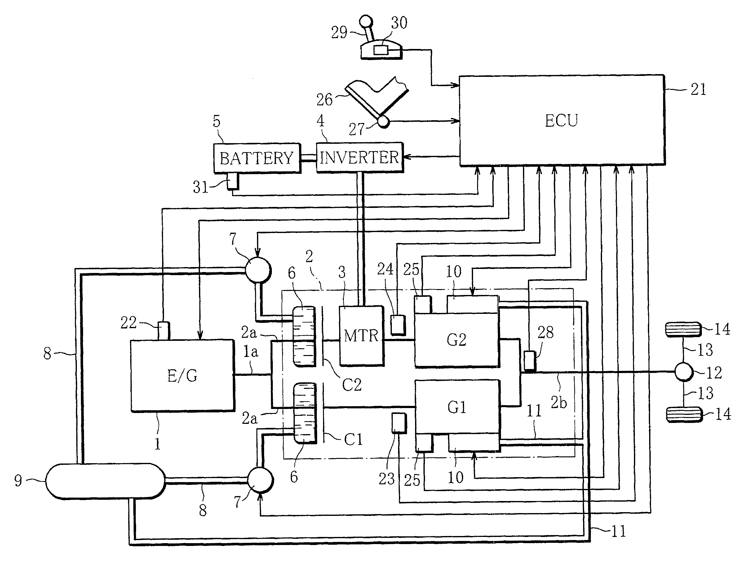
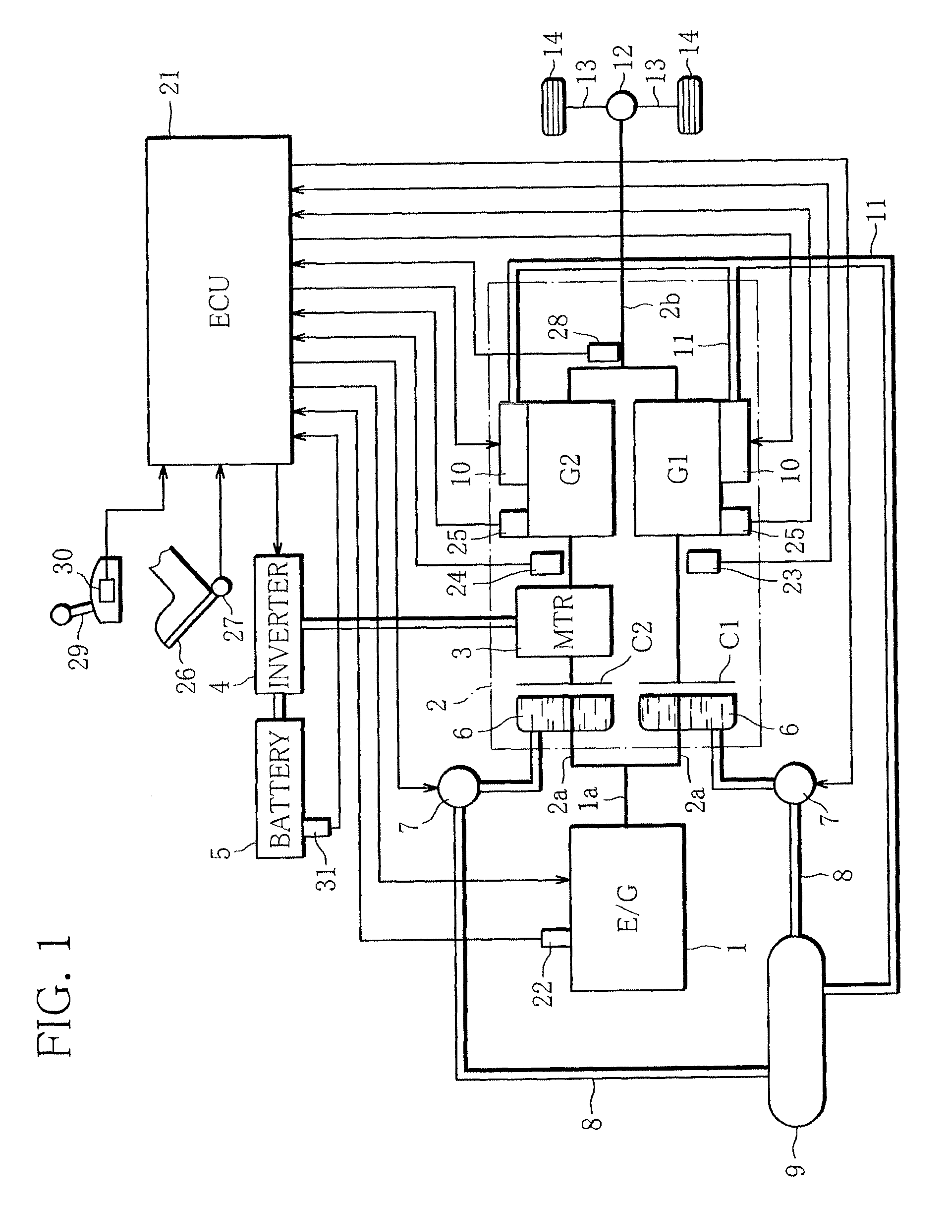
[0031]FIG. 1 is a diagram showing an overall arrangement of the battery warm-up apparatus of the hybrid electric vehicle according to the present embodiment. The vehicle is equipped with a diesel engine (hereafter referred to as the engine) 1 as a traveling power source. The engine 1 is configured as a so-called common rail type engine that supplies high-pressure fuel, which is accumulated in a common rail by a pressure pump, to fuel injection valves of respective cylinders, and injects the fuel into the cylinders in response to opening of the fuel injection valves.

[0032]An output shaft 1a of the engine 1 is projected rearward in the vehicle 1 from the engine 1, and connected to an input shaft 2a of an automatic transmission (hereafter referred to merely as the transmission) 2. The transmiss...


PUM


Abstract

A hybrid electric vehicle includes a wet clutch device that establishes and interrupts a connection between an engine and an electric motor, and a transmission switchable between a driving range in which driving force can be transmitted to driving wheels and a non-driving range in which transmission of the driving force is interrupted. When a battery temperature is greater than a warm-up determination value while the vehicle is at a standstill with the transmission switched to the non-driving range, the wet clutch device is kept disengaged. When the battery temperature is less than the warm-up determination value, a battery warm-up control unit switches the wet clutch device into engaged state to connect the engine and the electric motor together and vary driving force of the electric motor alternately to a positive side and a negative side so as to repeatedly charge and discharge the battery.

Description

TECHNICAL FIELD[0001]Exemplary embodiments of the present invention relate to a hybrid electric vehicle powered by an engine and an electric motor, and in particular to a battery warm-up apparatus that prevents degradation in the charge-discharge performance of a travelling battery.BACKGROUND OF THE INVENTION[0002]In recent years, hybrid electric vehicles of various types, such as a series type and a parallel type, have been put into practical use. In such hybrid electric vehicles, electrical power supplied from a travelling battery causes an electric motor to act as a motor to move the vehicle, while the electric motor is caused to act as a generator using SOC (state of charge), which indicates the remaining capacity of a battery, as an indicator, and the battery is charged with power generated by the electric motor so that SOC can be maintained in a predetermined range. Thus, the travelling performance of a vehicle using an electric motor is greatly influenced by the charge-discha...

Claims


Application Information

Patent Timeline
Patent Type & Authority Patents(United States)
IPC IPC(8): B60W20/00B60W10/02B60W10/26B60W10/06B60L11/14B60K6/48B60W10/08B60L11/18B60L7/14F16H3/00B60L50/16
CPCB60W20/00B60K6/48B60L7/14B60L11/14B60L11/1872B60L11/1875B60W10/02B60W10/023B60W10/06B60W10/08B60W10/26B60L2210/40B60L2240/12B60L2240/441B60L2240/545B60W2510/246B60W2600/00B60W2710/023B60W2710/246F16H3/006Y02T10/6221Y02T10/6286Y02T10/70Y02T10/7005Y02T10/705Y02T10/7077Y02T10/7241Y10S903/93B60L50/16B60L58/25B60L58/27Y02T10/62Y02T10/72Y02T10/7072B60W20/15B60W2556/00
Inventor KIUCHI, TATSUO
Owner DAIMLER AG
Why Eureka
Try Eureka